TOP Contributors

  1. MIKROE (2784 codes)
  2. Alcides Ramos (403 codes)
  3. Shawon Shahryiar (307 codes)
  4. jm_palomino (132 codes)
  5. Bugz Bensce (97 codes)
  6. S P (73 codes)
  7. dany (71 codes)
  8. MikroBUS.NET Team (35 codes)
  9. NART SCHINACKOW (34 codes)
  10. Armstrong Subero (27 codes)

Most Downloaded

  1. Timer Calculator (140956 times)
  2. FAT32 Library (73508 times)
  3. Network Ethernet Library (58321 times)
  4. USB Device Library (48508 times)
  5. Network WiFi Library (44132 times)
  6. FT800 Library (43686 times)
  7. GSM click (30546 times)
  8. mikroSDK (29286 times)
  9. PID Library (27220 times)
  10. microSD click (26931 times)
Libstock prefers package manager

Package Manager

We strongly encourage users to use Package manager for sharing their code on Libstock website, because it boosts your efficiency and leaves the end user with no room for error. [more info]

< Back
mikroSDK Library

ADC 8 click

Rating:

5

Author: MIKROE

Last Updated: 2019-03-18

Package Version: 1.0.0.0

mikroSDK Library: 1.0.0.0

Category: ADC

Downloaded: 4385 times

Not followed.

License: MIT license  

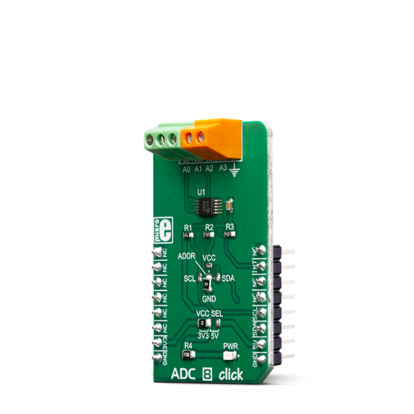
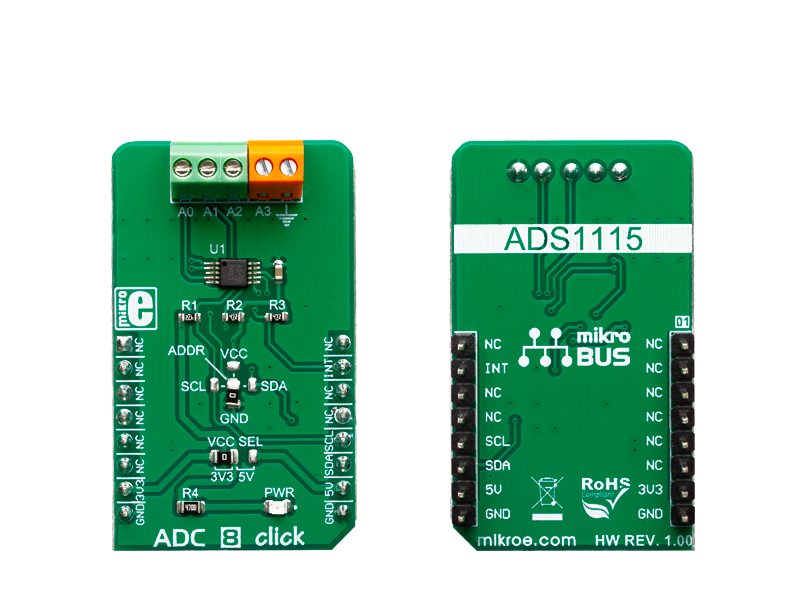
ADC 8 Click is a high precision, low-power, 16-bit analog-to-digital converter (ADC), based around the ADS1115 IC. It is capable of sampling signals on four single-ended or two differential input channels.

No Abuse Reported

Do you want to subscribe in order to receive notifications regarding "ADC 8 click" changes.

Do you want to unsubscribe in order to stop receiving notifications regarding "ADC 8 click" changes.

Do you want to report abuse regarding "ADC 8 click".

  • mikroSDK Library 2.0.0.0
  • Comments (0)
DOWNLOAD LINK RELATED COMPILER CONTAINS
mikroBasic PRO for ARM
  • lib
  • src
  • exa
  • hlp
  • hex
  • sch
  • pcb
  • doc
mikroBasic PRO for AVR
  • lib
  • src
  • exa
  • hlp
  • hex
  • sch
  • pcb
  • doc
mikroBasic PRO for dsPIC30/33 & PIC24
  • lib
  • src
  • exa
  • hlp
  • hex
  • sch
  • pcb
  • doc
mikroBasic PRO for FT90x
  • lib
  • src
  • exa
  • hlp
  • hex
  • sch
  • pcb
  • doc
mikroBasic PRO for PIC
  • lib
  • src
  • exa
  • hlp
  • hex
  • sch
  • pcb
  • doc
mikroBasic PRO for PIC32
  • lib
  • src
  • exa
  • hlp
  • hex
  • sch
  • pcb
  • doc
mikroC PRO for ARM
  • lib
  • src
  • exa
  • hlp
  • hex
  • sch
  • pcb
  • doc
mikroC PRO for AVR
  • lib
  • src
  • exa
  • hlp
  • hex
  • sch
  • pcb
  • doc
mikroC PRO for dsPIC30/33 & PIC24
  • lib
  • src
  • exa
  • hlp
  • hex
  • sch
  • pcb
  • doc
mikroC PRO for FT90x
  • lib
  • src
  • exa
  • hlp
  • hex
  • sch
  • pcb
  • doc
mikroC PRO for PIC
  • lib
  • src
  • exa
  • hlp
  • hex
  • sch
  • pcb
  • doc
mikroC PRO for PIC32
  • lib
  • src
  • exa
  • hlp
  • hex
  • sch
  • pcb
  • doc
mikroPascal PRO for ARM
  • lib
  • src
  • exa
  • hlp
  • hex
  • sch
  • pcb
  • doc
mikroPascal PRO for AVR
  • lib
  • src
  • exa
  • hlp
  • hex
  • sch
  • pcb
  • doc
mikroPascal PRO for dsPIC30/33 & PIC24
  • lib
  • src
  • exa
  • hlp
  • hex
  • sch
  • pcb
  • doc
mikroPascal PRO for FT90x
  • lib
  • src
  • exa
  • hlp
  • hex
  • sch
  • pcb
  • doc
mikroPascal PRO for PIC
  • lib
  • src
  • exa
  • hlp
  • hex
  • sch
  • pcb
  • doc
mikroPascal PRO for PIC32
  • lib
  • src
  • exa
  • hlp
  • hex
  • sch
  • pcb
  • doc

mikroSDK Library Blog

ADC 8 click

ADC 8 click

Native view of the ADC 8 click board.

View full image
ADC 8 click

ADC 8 click

Front and back view of the ADC 8 click board.

View full image

Library Description

The library contains functions for the complete communication of the MCU with click. The user can use functions to read the ADC values and voltage on the channel. The library also offers functions for writting data into the register and reading data from the register, as well as the configuration of the device for successful measurement.

Key functions:

  • float adc8_getVoltage(uint8_t channel) - Read Voltage in mV
  • uint16_t adc8_getADCValue(uint8_t channel) - Get ADC value reads from the channel
  • void adc8_deviceConfig(uint16_t cfg) - Device configuration for measurement

Examples description

The application is composed of the three sections :

  • System Initialization - Initializes I2C module and sets INT pin as INPUT
  • Application Initialization - Initialization driver init and configuration device for measurement.
  • Application Task - Reads voltage from each channel one by one and the voltage difference between specified channels

Note: On the input channel AIN0,AIN1,AIN2 and AIN3 sets maximum voltage GND - 0.3V < VIN > VDD + 0.3V.

void applicationTask()
{
    // Single channel
    vSingle_CH0 = adc8_getVoltage(_ADC8_SINGLE_CHANNEL_0);
    vSingle_CH1 = adc8_getVoltage(_ADC8_SINGLE_CHANNEL_1);
    vSingle_CH2 = adc8_getVoltage(_ADC8_SINGLE_CHANNEL_2);
    vSingle_CH3 = adc8_getVoltage(_ADC8_SINGLE_CHANNEL_3);
    
    mikrobus_logWrite("______________________________________________", _LOG_LINE);
    mikrobus_logWrite(" Channel |  CH 0  |  CH 1  |  CH 2  |  CH 3  |", _LOG_LINE);
    mikrobus_logWrite(" Single  |", _LOG_TEXT);
    
    IntToStr(vSingle_CH0, demoText);
    mikrobus_logWrite(demoText, _LOG_TEXT);
    mikrobus_logWrite("  |", _LOG_TEXT);

    IntToStr(vSingle_CH1, demoText);
    mikrobus_logWrite(demoText, _LOG_TEXT);
    mikrobus_logWrite("  |", _LOG_TEXT);
    
    IntToStr(vSingle_CH2, demoText);
    mikrobus_logWrite(demoText, _LOG_TEXT);
    mikrobus_logWrite("  |", _LOG_TEXT);
    
    IntToStr(vSingle_CH3, demoText);
    mikrobus_logWrite(demoText, _LOG_TEXT);
    mikrobus_logWrite("  |", _LOG_LINE);
    
    // Diff channel
    vDiff_CH01 = adc8_getVoltage(_ADC8_DIFF_CHANNEL_0_1);
    vDiff_CH03 = adc8_getVoltage(_ADC8_DIFF_CHANNEL_0_3);
    vDiff_CH13 = adc8_getVoltage(_ADC8_DIFF_CHANNEL_1_3);
    vDiff_CH23 = adc8_getVoltage(_ADC8_DIFF_CHANNEL_2_3);
    
    mikrobus_logWrite("______________________________________________", _LOG_LINE);
    mikrobus_logWrite(" Channel | CH 0-1 | CH 0-3 | CH 1-3 | CH 2-3 |", _LOG_LINE);
    mikrobus_logWrite("  Diff   |", _LOG_TEXT);

    IntToStr(vDiff_CH01, demoText);
    mikrobus_logWrite(demoText, _LOG_TEXT);
    mikrobus_logWrite("  |", _LOG_TEXT);

    IntToStr(vDiff_CH03, demoText);
    mikrobus_logWrite(demoText, _LOG_TEXT);
    mikrobus_logWrite("  |", _LOG_TEXT);

    IntToStr(vDiff_CH13, demoText);
    mikrobus_logWrite(demoText, _LOG_TEXT);
    mikrobus_logWrite("  |", _LOG_TEXT);

    IntToStr(vDiff_CH23, demoText);
    mikrobus_logWrite(demoText, _LOG_TEXT);
    mikrobus_logWrite("  |", _LOG_LINE);
    
    mikrobus_logWrite("|--------------------------------------------|", _LOG_LINE);
    Delay_1sec();
}

Other mikroE Libraries used in the example:

  • I2C
  • Conversions

Additional notes and informations

Depending on the development board you are using, you may need USB UART clickUSB UART 2 click or RS232 click to connect to your PC, for development systems with no UART to USB interface available on the board. The terminal available in all MikroElektronika compilers, or any other terminal application of your choice, can be used to read the message.

ALSO FROM THIS AUTHOR

LR 4 Click

0

LR 4 Click is a compact add-on board that contains a long-range transceiver. This board features the 32001353, RF technology-based SRD transceiver, which operates at a frequency of 868MHz from Mipot.

[Learn More]

4Dot-Matrix R Click

0

4Dot-Matrix R Click is a display device Click board™, which contains a four-digit dot matrix display module, labeled as SLO2016.

[Learn More]

Accel 21 Click

0

Accel 21 Click is a compact add-on board that contains an acceleration sensor. This board features the MIS2DH, a high-performance three-axis accelerometer from STMicroelectronics. The MIS2DH allows selectable full-scale acceleration measurements in ranges of ±2g, ±4g, ±8g, or ±16g in three axes with a configurable host interface that supports both SPI and I2C serial communication. It also supports high-resolution and low-power operating modes, allowing maximum flexibility to meet various use case needs.

[Learn More]