TOP Contributors

  1. MIKROE (2784 codes)
  2. Alcides Ramos (402 codes)
  3. Shawon Shahryiar (307 codes)
  4. jm_palomino (129 codes)
  5. Bugz Bensce (97 codes)
  6. S P (73 codes)
  7. dany (71 codes)
  8. MikroBUS.NET Team (35 codes)
  9. NART SCHINACKOW (34 codes)
  10. Armstrong Subero (27 codes)

Most Downloaded

  1. Timer Calculator (140818 times)
  2. FAT32 Library (73433 times)
  3. Network Ethernet Library (58243 times)
  4. USB Device Library (48412 times)
  5. Network WiFi Library (44043 times)
  6. FT800 Library (43612 times)
  7. GSM click (30500 times)
  8. mikroSDK (29203 times)
  9. PID Library (27192 times)
  10. microSD click (26876 times)
Libstock prefers package manager

Package Manager

We strongly encourage users to use Package manager for sharing their code on Libstock website, because it boosts your efficiency and leaves the end user with no room for error. [more info]

< Back
mikroSDK Library

6DOF IMU 8 click

Rating:

5

Author: MIKROE

Last Updated: 2019-04-11

Package Version: 1.0.0.0

mikroSDK Library: 1.0.0.0

Category: Motion

Downloaded: 4550 times

Not followed.

License: MIT license  

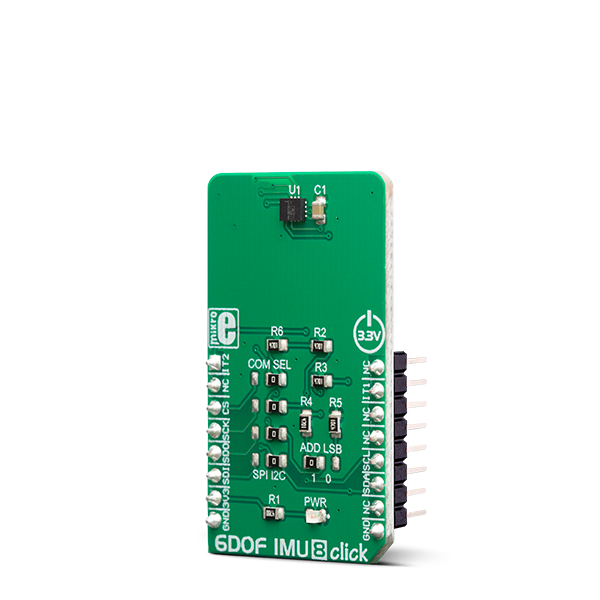
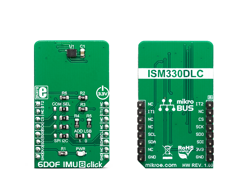
6DOF IMU 8 click is an advanced 6-axis motion tracking Click board, which utilizes the ISM330DLC, a high-performance System in Package (SiP), equipped with a 3-axis gyroscope, and a 3-axis accelerometer.

No Abuse Reported

Do you want to subscribe in order to receive notifications regarding "6DOF IMU 8 click" changes.

Do you want to unsubscribe in order to stop receiving notifications regarding "6DOF IMU 8 click" changes.

Do you want to report abuse regarding "6DOF IMU 8 click".

  • mikroSDK Library 2.0.0.0
  • Comments (0)
DOWNLOAD LINK RELATED COMPILER CONTAINS
mikroBasic PRO for ARM
  • lib
  • src
  • exa
  • hlp
  • hex
  • sch
  • pcb
  • doc
mikroBasic PRO for AVR
  • lib
  • src
  • exa
  • hlp
  • hex
  • sch
  • pcb
  • doc
mikroBasic PRO for dsPIC30/33 & PIC24
  • lib
  • src
  • exa
  • hlp
  • hex
  • sch
  • pcb
  • doc
mikroBasic PRO for FT90x
  • lib
  • src
  • exa
  • hlp
  • hex
  • sch
  • pcb
  • doc
mikroBasic PRO for PIC
  • lib
  • src
  • exa
  • hlp
  • hex
  • sch
  • pcb
  • doc
mikroBasic PRO for PIC32
  • lib
  • src
  • exa
  • hlp
  • hex
  • sch
  • pcb
  • doc
mikroC PRO for ARM
  • lib
  • src
  • exa
  • hlp
  • hex
  • sch
  • pcb
  • doc
mikroC PRO for AVR
  • lib
  • src
  • exa
  • hlp
  • hex
  • sch
  • pcb
  • doc
mikroC PRO for dsPIC30/33 & PIC24
  • lib
  • src
  • exa
  • hlp
  • hex
  • sch
  • pcb
  • doc
mikroC PRO for FT90x
  • lib
  • src
  • exa
  • hlp
  • hex
  • sch
  • pcb
  • doc
mikroC PRO for PIC
  • lib
  • src
  • exa
  • hlp
  • hex
  • sch
  • pcb
  • doc
mikroC PRO for PIC32
  • lib
  • src
  • exa
  • hlp
  • hex
  • sch
  • pcb
  • doc
mikroPascal PRO for ARM
  • lib
  • src
  • exa
  • hlp
  • hex
  • sch
  • pcb
  • doc
mikroPascal PRO for AVR
  • lib
  • src
  • exa
  • hlp
  • hex
  • sch
  • pcb
  • doc
mikroPascal PRO for dsPIC30/33 & PIC24
  • lib
  • src
  • exa
  • hlp
  • hex
  • sch
  • pcb
  • doc
mikroPascal PRO for FT90x
  • lib
  • src
  • exa
  • hlp
  • hex
  • sch
  • pcb
  • doc
mikroPascal PRO for PIC
  • lib
  • src
  • exa
  • hlp
  • hex
  • sch
  • pcb
  • doc
mikroPascal PRO for PIC32
  • lib
  • src
  • exa
  • hlp
  • hex
  • sch
  • pcb
  • doc

mikroSDK Library Blog

6DOF IMU 8 click

6DOF IMU 8 click

Native view of the 6DOF IMU 8 click board.

View full image
6DOF IMU 8 click

6DOF IMU 8 click

Front and back view of the 6DOF IMU 8 click board.

View full image

Library Description

The library performs a control of the 6DOF IMU 8 Click board, which is able to measure the accelerometer, gyroscope, temperature and magnetometer axis data. The full scale range and data rate are adjustable for each measurement. 6DOF IMU 8 Click board has two serial interface, SPI and I2C. There is also a more others settings and configurations which the user can use to set a device for the desired operation mode. For more details check documentation.

Key functions:

  • void c6dofimu8_getData( T_c6dofimu8_axis *accelOut, T_c6dofimu8_axis *gyroOut, int8_t *tempOut ) - Function performs a data reading and all necessary calculations to get accelerometer, gyroscope and temperature data.
  • T_C6DOFIMU8_RETVAL c6dofimu8_setFSR( uint8_t gyro_fsr, uint8_t accel_fsr ) - Function selects a measurement full scale range.
  • T_C6DOFIMU8_RETVAL c6dofimu8_setODR( uint8_t gyro_odr, uint8_t accel_odr ) - Function selects a measurement output data rate.

Examples description

The application is composed of the three sections :

  • System Initialization - Initializes peripherals and pins.
  • Application Initialization - Initializes SPI interface and performs a device software reset and configuration.
  • Application Task - (code snippet) - Waits until any new data is entered to the data registers and then reads the accelerometer, gyroscope and temperature data which will be converted and calculated to the properly units every 300ms.
void applicationTask()
{
    dataReady = c6dofimu8_getDRDYStatus( _C6DOFIMU8_TEMP_DRDY_MASK | _C6DOFIMU8_G_DRDY_MASK | _C6DOFIMU8_XL_DRDY_MASK );
    while (dataReady == _C6DOFIMU8_EVENT_NOT_DETECTED)
    {
        dataReady = c6dofimu8_getDRDYStatus( _C6DOFIMU8_TEMP_DRDY_MASK | _C6DOFIMU8_G_DRDY_MASK | _C6DOFIMU8_XL_DRDY_MASK );
    }

    c6dofimu8_getData( &accel_data, &gyro_data, &temperature );

    mikrobus_logWrite( "** Accelerometer values :", _LOG_LINE );
    logAxis( &accel_data, &accelUnit[0] );
    mikrobus_logWrite( "", _LOG_LINE );

    mikrobus_logWrite( "** Gyroscope values :", _LOG_LINE );
    logAxis( &gyro_data, &gyroUnit[0] );
    mikrobus_logWrite( "", _LOG_LINE );

    mikrobus_logWrite( "** Temperature value : ", _LOG_TEXT );
    ShortToStr( temperature, text );
    mikrobus_logWrite( text, _LOG_TEXT );
    mikrobus_logWrite( tempUnit, _LOG_LINE );
    mikrobus_logWrite( "-------------------------------------------------", _LOG_LINE );
    mikrobus_logWrite( "", _LOG_LINE );

    Delay_ms( 300 );
}

Additional Functions :

  • floatCut - Makes to float values be rounded on two decimal places.
  • logAxis - Logs a axis values for the desired measured data on the uart terminal.

Other mikroE Libraries used in the example:

  • I2C
  • UART
  • SPI

Additional notes and informations

Depending on the development board you are using, you may need USB UART clickUSB UART 2 click or RS232 click to connect to your PC, for development systems with no UART to USB interface available on the board. The terminal available in all MikroElektronika compilers, or any other terminal application of your choice, can be used to read the message.

ALSO FROM THIS AUTHOR

PWR Meter 3 30A Click

0

PWR Meter 3 Click - 30A is a compact add-on board that measures voltage and current through the connected load. This board features the ACS37800KMACTR-030B3-I2C, an I2C-configurable power monitoring solution from Allegro MicroSystems, which simplifies the addition of power monitoring to many AC/DC powered systems. The ACS37800KMACLU-090B3-I2C Hall-effect-based current sensing technology achieves reinforced isolation ratings (4800 VRMS) alongside a reliable ±30A bidirectional current sensing. It also has two LED indicators for the realization of visual detection of some anomalies in operation, such as under/overvoltage and fast overcurrent fault detection.

[Learn More]

Light Temp click

5

Light Temp Click is a dual-channel LED driver, designed to be used in tunable Smart Connected Lighting (SCL) applications. It is based on the AL1782, a dual-channel PWM dimmable linear LED driver.

[Learn More]

NeoMesh 2 Click

0

NeoMesh 2 Click is a compact add-on board with a low-power, long-range transceiver, ideal for Mesh wireless networking. This board features the NC2400, a wireless Mesh network module from NeoCortec. With an additional antenna that MikroE offers connected to the module’s u.Fl connector, you can create a fully functional wireless Mesh network node that will work in the Sub-GHz frequency band of 2.4GHz. The module has a generic application layer that can be configured to suit applications.

[Learn More]