TOP Contributors

  1. MIKROE (2784 codes)
  2. Alcides Ramos (387 codes)
  3. Shawon Shahryiar (307 codes)
  4. jm_palomino (120 codes)
  5. Bugz Bensce (97 codes)
  6. S P (73 codes)
  7. dany (71 codes)
  8. MikroBUS.NET Team (35 codes)
  9. NART SCHINACKOW (34 codes)
  10. Armstrong Subero (27 codes)

Most Downloaded

  1. Timer Calculator (140168 times)
  2. FAT32 Library (72622 times)
  3. Network Ethernet Library (57644 times)
  4. USB Device Library (47957 times)
  5. Network WiFi Library (43554 times)
  6. FT800 Library (42942 times)
  7. GSM click (30140 times)
  8. mikroSDK (28670 times)
  9. PID Library (27057 times)
  10. microSD click (26552 times)
Libstock prefers package manager

Package Manager

We strongly encourage users to use Package manager for sharing their code on Libstock website, because it boosts your efficiency and leaves the end user with no room for error. [more info]

< Back
mikroSDK Library

ECG 5 click

Rating:

5

Author: MIKROE

Last Updated: 2019-04-22

Package Version: 1.0.0.0

mikroSDK Library: 1.0.0.0

Category: Biometrics

Downloaded: 3804 times

Not followed.

License: MIT license  

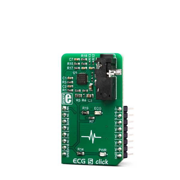
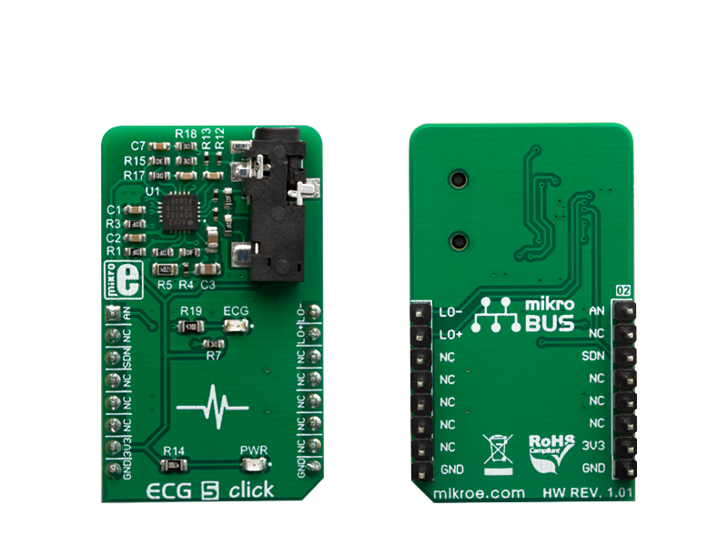
ECG 5 click can be used for the development of ECG and Heart-Rate (HR) applications. The Click board features the AD8232, an integrated bio-signal front end.

No Abuse Reported

Do you want to subscribe in order to receive notifications regarding "ECG 5 click" changes.

Do you want to unsubscribe in order to stop receiving notifications regarding "ECG 5 click" changes.

Do you want to report abuse regarding "ECG 5 click".

  • mikroSDK Library 2.0.0.0
  • Comments (0)
DOWNLOAD LINK RELATED COMPILER CONTAINS
mikroBasic PRO for ARM
  • lib
  • src
  • exa
  • hlp
  • hex
  • sch
  • pcb
  • doc
mikroBasic PRO for AVR
  • lib
  • src
  • exa
  • hlp
  • hex
  • sch
  • pcb
  • doc
mikroBasic PRO for dsPIC30/33 & PIC24
  • lib
  • src
  • exa
  • hlp
  • hex
  • sch
  • pcb
  • doc
mikroBasic PRO for FT90x
  • lib
  • src
  • exa
  • hlp
  • hex
  • sch
  • pcb
  • doc
mikroBasic PRO for PIC
  • lib
  • src
  • exa
  • hlp
  • hex
  • sch
  • pcb
  • doc
mikroBasic PRO for PIC32
  • lib
  • src
  • exa
  • hlp
  • hex
  • sch
  • pcb
  • doc
mikroC PRO for ARM
  • lib
  • src
  • exa
  • hlp
  • hex
  • sch
  • pcb
  • doc
mikroC PRO for AVR
  • lib
  • src
  • exa
  • hlp
  • hex
  • sch
  • pcb
  • doc
mikroC PRO for dsPIC30/33 & PIC24
  • lib
  • src
  • exa
  • hlp
  • hex
  • sch
  • pcb
  • doc
mikroC PRO for FT90x
  • lib
  • src
  • exa
  • hlp
  • hex
  • sch
  • pcb
  • doc
mikroC PRO for PIC
  • lib
  • src
  • exa
  • hlp
  • hex
  • sch
  • pcb
  • doc
mikroC PRO for PIC32
  • lib
  • src
  • exa
  • hlp
  • hex
  • sch
  • pcb
  • doc
mikroPascal PRO for ARM
  • lib
  • src
  • exa
  • hlp
  • hex
  • sch
  • pcb
  • doc
mikroPascal PRO for AVR
  • lib
  • src
  • exa
  • hlp
  • hex
  • sch
  • pcb
  • doc
mikroPascal PRO for dsPIC30/33 & PIC24
  • lib
  • src
  • exa
  • hlp
  • hex
  • sch
  • pcb
  • doc
mikroPascal PRO for FT90x
  • lib
  • src
  • exa
  • hlp
  • hex
  • sch
  • pcb
  • doc
mikroPascal PRO for PIC
  • lib
  • src
  • exa
  • hlp
  • hex
  • sch
  • pcb
  • doc
mikroPascal PRO for PIC32
  • lib
  • src
  • exa
  • hlp
  • hex
  • sch
  • pcb
  • doc

mikroSDK Library Blog

ECG 5 click

ECG 5 click

Native view of the ECG 5 click board.

View full image
ECG 5 click

ECG 5 click

Front and back view of the ECG 5 click board.

View full image

Library Description

The library performs a device mode setting (Normal or Shutdown) and a leads off detection checking. Also the library initializes GPIO driver. For more details check documentation.

Key functions:

  • void ecg5_setMode( uint8_t state ) - Function performs a device mode setting.
  • T_ECG5_RETVAL ecg5_check_LOD_negative( void ) - In DC Leads Off Detection Mode, LOD- is high when the electrode to -IN is disconnected, and it is low when connected. In AC Leads Off Detection Mode, LOD- is always low.
  • void ecg5_gpioDriverInit(T_ECG5_P gpioObj) - Function initializes GPIO driver.

Examples description

The application is composed of the three sections :

  • System Initialization - Initializes peripherals and pins.
  • Application Initialization - Initializes GPIO driver, selects a desired mode of the device and performs the ADC and timer interrupt initialization.
  • Application Task - (code snippet) - When the timer has reached the set value (4ms), the ADC converted result will be read and sent to the serial plotter.
void applicationTask()
{
    if (respReady == RESPONSE_READY)
    {
        respReady = RESPONSE_NOT_READY;
        adcValue = ADC_Get_Sample( 0 );
    
        WordToStr( adcValue, text );
        mikrobus_logWrite( text, _LOG_TEXT );
        mikrobus_logWrite( ",", _LOG_TEXT );
        LongWordToStr( plotX, text );
        mikrobus_logWrite( text, _LOG_LINE );
    
        if (plotX == 0xFFFFFFFF)
        {
            plotX = 0;
        }
        else
        {
            plotX++;
        }
    }
}

Other mikroE Libraries used in the example:

  • ADC
  • UART
  • Conversions

Additional notes and informations

Depending on the development board you are using, you may need USB UART clickUSB UART 2 click or RS232 click to connect to your PC, for development systems with no UART to USB interface available on the board. The terminal available in all MikroElektronika compilers, or any other terminal application of your choice, can be used to read the message.

ALSO FROM THIS AUTHOR

RMS to DC click

7

RMS to DC click is a Click board that is used to convert the RMS of the input signal into a DC voltage, with a value directly readable over the I2C interface. The Click board is equipped with the LTC1968, an RMS-to-DC converter IC, which outputs an analog voltage depending on the RMS value of the input signal.

[Learn More]

Secure click

1

Secure click carries the ATECC508A cryptographic coprocessor with secure hardware-based key storage. The click is designed to run on either 3.3V or 5V power supply. It communicates with the target microcontroller over I2C interface.

[Learn More]

Button R Click

0

Button R Click is the simplest solution for adding a single pushbutton to your design. The button itself is transparent, 6.8mm in diameter and has a red LED backlight. When pressed, it sends an interrupt signal to the target board microcontroller. The backlight LED is controlled separately through the mikroBUS PWM pin, so you can program all kinds of patterns (varying level of light intensity or rate of blinking on subsequent button presses). The board can use either a 3.3V or a 5V power supply.

[Learn More]