TOP Contributors

  1. MIKROE (2784 codes)
  2. Alcides Ramos (403 codes)
  3. Shawon Shahryiar (307 codes)
  4. jm_palomino (132 codes)
  5. Bugz Bensce (97 codes)
  6. S P (73 codes)
  7. dany (71 codes)
  8. MikroBUS.NET Team (35 codes)
  9. NART SCHINACKOW (34 codes)
  10. Armstrong Subero (27 codes)

Most Downloaded

  1. Timer Calculator (140941 times)
  2. FAT32 Library (73501 times)
  3. Network Ethernet Library (58318 times)
  4. USB Device Library (48484 times)
  5. Network WiFi Library (44090 times)
  6. FT800 Library (43662 times)
  7. GSM click (30545 times)
  8. mikroSDK (29266 times)
  9. PID Library (27205 times)
  10. microSD click (26929 times)
Libstock prefers package manager

Package Manager

We strongly encourage users to use Package manager for sharing their code on Libstock website, because it boosts your efficiency and leaves the end user with no room for error. [more info]

< Back
mikroSDK Library

Ambient 7 click

Rating:

5

Author: MIKROE

Last Updated: 2019-06-13

Package Version: 1.0.0.0

mikroSDK Library: 1.0.0.0

Category: Optical

Downloaded: 3635 times

Not followed.

License: MIT license  

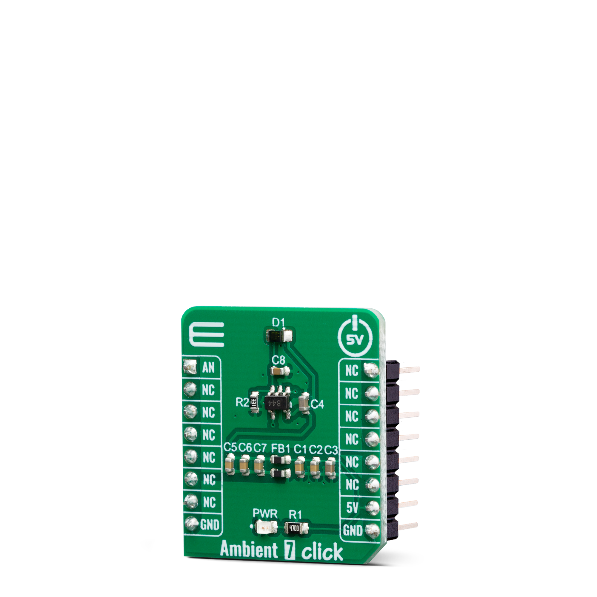
Ambient 7 Click is a light intensity-sensing and measuring Click board, which features an accurate light-intensity sensor labeled as SFH 5701 A01, made by Osram Opto Semiconductors.

No Abuse Reported

Do you want to subscribe in order to receive notifications regarding "Ambient 7 click" changes.

Do you want to unsubscribe in order to stop receiving notifications regarding "Ambient 7 click" changes.

Do you want to report abuse regarding "Ambient 7 click".

  • mikroSDK Library 2.0.0.0
  • Comments (0)
DOWNLOAD LINK RELATED COMPILER CONTAINS
mikroBasic PRO for ARM
  • lib
  • src
  • exa
  • hlp
  • hex
  • sch
  • pcb
  • doc
mikroBasic PRO for AVR
  • lib
  • src
  • exa
  • hlp
  • hex
  • sch
  • pcb
  • doc
mikroBasic PRO for dsPIC30/33 & PIC24
  • lib
  • src
  • exa
  • hlp
  • hex
  • sch
  • pcb
  • doc
mikroBasic PRO for FT90x
  • lib
  • src
  • exa
  • hlp
  • hex
  • sch
  • pcb
  • doc
mikroBasic PRO for PIC
  • lib
  • src
  • exa
  • hlp
  • hex
  • sch
  • pcb
  • doc
mikroBasic PRO for PIC32
  • lib
  • src
  • exa
  • hlp
  • hex
  • sch
  • pcb
  • doc
mikroC PRO for ARM
  • lib
  • src
  • exa
  • hlp
  • hex
  • sch
  • pcb
  • doc
mikroC PRO for AVR
  • lib
  • src
  • exa
  • hlp
  • hex
  • sch
  • pcb
  • doc
mikroC PRO for dsPIC30/33 & PIC24
  • lib
  • src
  • exa
  • hlp
  • hex
  • sch
  • pcb
  • doc
mikroC PRO for FT90x
  • lib
  • src
  • exa
  • hlp
  • hex
  • sch
  • pcb
  • doc
mikroC PRO for PIC
  • lib
  • src
  • exa
  • hlp
  • hex
  • sch
  • pcb
  • doc
mikroC PRO for PIC32
  • lib
  • src
  • exa
  • hlp
  • hex
  • sch
  • pcb
  • doc
mikroPascal PRO for ARM
  • lib
  • src
  • exa
  • hlp
  • hex
  • sch
  • pcb
  • doc
mikroPascal PRO for AVR
  • lib
  • src
  • exa
  • hlp
  • hex
  • sch
  • pcb
  • doc
mikroPascal PRO for dsPIC30/33 & PIC24
  • lib
  • src
  • exa
  • hlp
  • hex
  • sch
  • pcb
  • doc
mikroPascal PRO for FT90x
  • lib
  • src
  • exa
  • hlp
  • hex
  • sch
  • pcb
  • doc
mikroPascal PRO for PIC
  • lib
  • src
  • exa
  • hlp
  • hex
  • sch
  • pcb
  • doc
mikroPascal PRO for PIC32
  • lib
  • src
  • exa
  • hlp
  • hex
  • sch
  • pcb
  • doc

mikroSDK Library Blog

Ambient 7 click

Ambient 7 click

Native view of the Ambient 7 click board.

View full image
Ambient 7 click

Ambient 7 click

Front and back view of the Ambient 7 click board.

View full image

Library Description

The library contains ADC functions to completely setting and reading the value from the ADC channel that sends Ambient click. The ambient light measurement resolution depends on the ADC resolution you use.

Key functions:

  • void ambient7_adcInit() - ADC init.
  • void ambient7_adcSetInputChannel() - ADC set input channel.
  • uint32_t ambient7_adcRead() - ADC read data.

Examples description

The application is composed of three sections :

  • System Initialization - Initializes UART for logging data.
  • Application Initialization - Initialization driver init and ADC init.
  • Application Task - Reads ADC value and this data logs to USBUART every 1 sec..
  • note - Illuminance range [EV] - from 0.01[lx] to 10k[lx] depending on the ADC you are using.
void applicationTask()
{
    uint16_t ADC_value;
    char demoText[ 50 ];
        
    ADC_value = ambient7_adcRead();
    
    WordToStr(ADC_value, demoText);
    mikrobus_logWrite(" ADC value: ", _LOG_TEXT);
    mikrobus_logWrite(demoText, _LOG_LINE);
    Delay_ms( 500 );
}

Other mikroE Libraries used in the example:

  • ADC Library.
  • Conversions Library.

Additional notes and informations

Depending on the development board you are using, you may need USB UART clickUSB UART 2 click or RS232 click to connect to your PC, for development systems with no UART to USB interface available on the board. The terminal available in all MikroElektronika compilers, or any other terminal application of your choice, can be used to read the message.

ALSO FROM THIS AUTHOR

Slider click

5

Slider click uses SPI bus communication to converts analog input voltage (VCC) to digital output value and shows this result on LED and USB UART terminal. Value of analog voltage depends on the slider position.

[Learn More]

8x8 G Click

0

8x8 G Click is a 64 LED matrix display Click board™, composed of SMD LEDs organized in 8 rows by 8 columns. It has a digital brightness control in 16 steps, it can control every LED in the display matrix independently, it blanks the display on power up to eliminate glitches and it requires a single resistor to control the current through all the LEDs at once, which simplifies the design. 8x8 G Click uses a fast SPI communication protocol, allowing fast display response and no lag.

[Learn More]

SolidSwitch 2 Click

0

SolidSwitch 2 Click is a compact add-on board that contains a load switching device. This board features the L9026, an automotive eight-channel relay driver from STMicroelectronics. The L9026 incorporates two high-side drivers and six configurable high-side/low-side drivers driven by an SPI interface or by two dedicated parallel inputs. Operating from an external power supply from 3V up to 18V, it provides a maximum current of 1A on its output terminals. It also offers advanced diagnostic and protection features such as short-to-ground, open load, overcurrent, and overtemperature detections.

[Learn More]