TOP Contributors

  1. MIKROE (2784 codes)
  2. Alcides Ramos (392 codes)
  3. Shawon Shahryiar (307 codes)
  4. jm_palomino (123 codes)
  5. Bugz Bensce (97 codes)
  6. S P (73 codes)
  7. dany (71 codes)
  8. MikroBUS.NET Team (35 codes)
  9. NART SCHINACKOW (34 codes)
  10. Armstrong Subero (27 codes)

Most Downloaded

  1. Timer Calculator (140546 times)
  2. FAT32 Library (73037 times)
  3. Network Ethernet Library (58043 times)
  4. USB Device Library (48215 times)
  5. Network WiFi Library (43826 times)
  6. FT800 Library (43295 times)
  7. GSM click (30359 times)
  8. mikroSDK (28990 times)
  9. PID Library (27116 times)
  10. microSD click (26722 times)
Libstock prefers package manager

Package Manager

We strongly encourage users to use Package manager for sharing their code on Libstock website, because it boosts your efficiency and leaves the end user with no room for error. [more info]

< Back
mikroSDK Library

Pressure 12 click

Rating:

5

Author: MIKROE

Last Updated: 2019-05-24

Package Version: 1.0.0.0

mikroSDK Library: 1.0.0.0

Category: Pressure

Downloaded: 4158 times

Not followed.

License: MIT license  

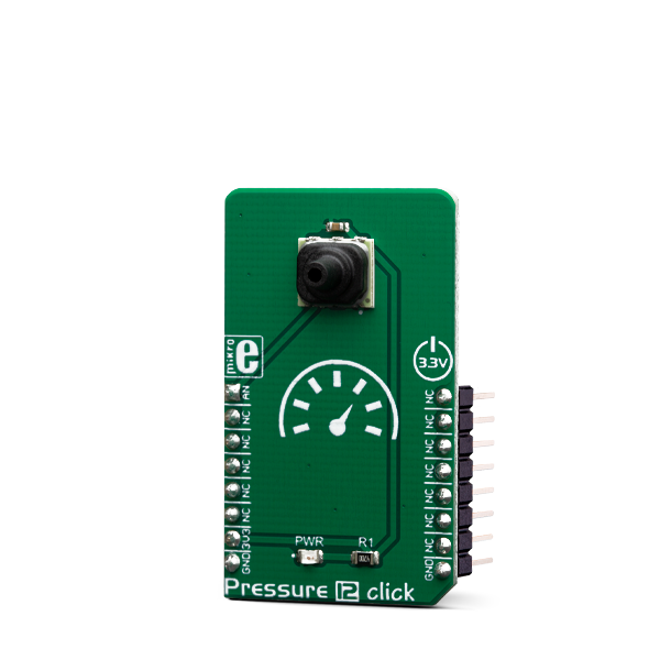
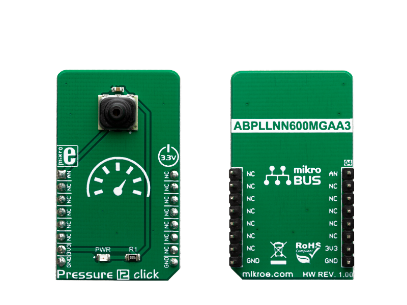
Pressure 12 click is a barometric gauge pressure measuring Click board, equipped with the Amplified Basic Pressure sensor series (ABP), which features a ratiometric analog output, which is proportional to the applied pressure.

No Abuse Reported

Do you want to subscribe in order to receive notifications regarding "Pressure 12 click" changes.

Do you want to unsubscribe in order to stop receiving notifications regarding "Pressure 12 click" changes.

Do you want to report abuse regarding "Pressure 12 click".

  • mikroSDK Library 2.0.0.0
  • Comments (0)
DOWNLOAD LINK RELATED COMPILER CONTAINS
mikroBasic PRO for ARM
  • lib
  • src
  • exa
  • hlp
  • hex
  • sch
  • pcb
  • doc
mikroBasic PRO for AVR
  • lib
  • src
  • exa
  • hlp
  • hex
  • sch
  • pcb
  • doc
mikroBasic PRO for dsPIC30/33 & PIC24
  • lib
  • src
  • exa
  • hlp
  • hex
  • sch
  • pcb
  • doc
mikroBasic PRO for FT90x
  • lib
  • src
  • exa
  • hlp
  • hex
  • sch
  • pcb
  • doc
mikroBasic PRO for PIC
  • lib
  • src
  • exa
  • hlp
  • hex
  • sch
  • pcb
  • doc
mikroBasic PRO for PIC32
  • lib
  • src
  • exa
  • hlp
  • hex
  • sch
  • pcb
  • doc
mikroC PRO for ARM
  • lib
  • src
  • exa
  • hlp
  • hex
  • sch
  • pcb
  • doc
mikroC PRO for AVR
  • lib
  • src
  • exa
  • hlp
  • hex
  • sch
  • pcb
  • doc
mikroC PRO for dsPIC30/33 & PIC24
  • lib
  • src
  • exa
  • hlp
  • hex
  • sch
  • pcb
  • doc
mikroC PRO for FT90x
  • lib
  • src
  • exa
  • hlp
  • hex
  • sch
  • pcb
  • doc
mikroC PRO for PIC
  • lib
  • src
  • exa
  • hlp
  • hex
  • sch
  • pcb
  • doc
mikroC PRO for PIC32
  • lib
  • src
  • exa
  • hlp
  • hex
  • sch
  • pcb
  • doc
mikroPascal PRO for ARM
  • lib
  • src
  • exa
  • hlp
  • hex
  • sch
  • pcb
  • doc
mikroPascal PRO for AVR
  • lib
  • src
  • exa
  • hlp
  • hex
  • sch
  • pcb
  • doc
mikroPascal PRO for dsPIC30/33 & PIC24
  • lib
  • src
  • exa
  • hlp
  • hex
  • sch
  • pcb
  • doc
mikroPascal PRO for FT90x
  • lib
  • src
  • exa
  • hlp
  • hex
  • sch
  • pcb
  • doc
mikroPascal PRO for PIC
  • lib
  • src
  • exa
  • hlp
  • hex
  • sch
  • pcb
  • doc
mikroPascal PRO for PIC32
  • lib
  • src
  • exa
  • hlp
  • hex
  • sch
  • pcb
  • doc

mikroSDK Library Blog

Pressure 12 click

Pressure 12 click

Native view of the Pressure 12 click board.

View full image
Pressure 12 click

Pressure 12 click

Front and back view of the Pressure 12 click board.

View full image

Library Description

The library contains all the necessary functions for converting ADC values to real voltages and pressure values.

Key functions:

  • float pressure12_getPressure(uint16_t adcValue) - Convert ADC value to Pressure data in mBar.
  • float pressure12_getVoltage(uint16_t adcValue) - Convert ADC value to Voltage in mV.
  • void pressure12_setMaxVoltage(float volt) - Sets max output voltage on the AN pin.

Examples description

The application is composed of three sections :

  • System Initialization - Initializes LOG for logging data.
  • Application Initialization - ADC init.
  • Application Task - Reads ADC value, Convert ADC data to Voltage[mV] on the AN pin and convert to Pressure data in mBar. All data logs to the USBUART every 1sec.
	void applicationTask()
{
    uint16_t ADC_value;
    float Voltage;
    float Pressure;
    char demoText[ 50 ];

    ADC_value = pressure12_adcRead();
    Voltage = pressure12_getVoltage(ADC_Value);
    Pressure = pressure12_getPressure(ADC_Value);

    WordToStr(ADC_value, demoText);
    mikrobus_logWrite(" ADC value: ", _LOG_TEXT);
    mikrobus_logWrite(demoText, _LOG_LINE);

    FloatToStr(Voltage, demoText);
    mikrobus_logWrite(" Voltage: ", _LOG_TEXT);
    mikrobus_logWrite(demoText, _LOG_TEXT );
    mikrobus_logWrite(" mV", _LOG_LINE );

    FloatToStr(Pressure, demoText);
    mikrobus_logWrite(" Pressure: ", _LOG_TEXT);
    mikrobus_logWrite(demoText, _LOG_TEXT);
    mikrobus_logWrite(" mBar", _LOG_LINE );

    mikrobus_logWrite("--------------------------", _LOG_LINE);
    Delay_ms( 1000 );
}

Other mikroE Libraries used in the example:

  • ADC Library
  • Conversion Library

Additional notes and informations

Depending on the development board you are using, you may need USB UART clickUSB UART 2 click or RS232 click to connect to your PC, for development systems with no UART to USB interface available on the board. The terminal available in all MikroElektronika compilers, or any other terminal application of your choice, can be used to read the message.

ALSO FROM THIS AUTHOR

SHT click

1

SHT click board caries new SHT3x-DIS by Sensirion. The board uses I2C bus to communicate with the target MCU and it can be powered with 3.3 V or 5 V power supply.

[Learn More]

UPS 3 Click

0

UPS 3 Click is a compact add-on board that represents a bidirectional active charge/balancing solution. This board features the LTC3110, a bidirectional buck-boost DC/DC regulator/charger combination with selectable operation modes for charging and system backup from Analog Devices. It can autonomously transition from Charge to Backup mode or switch modes based on an external command. A proprietary low noise switching algorithm optimizes efficiency with capacitor/battery voltages above, below, or equal to the system output voltage. Additional features include voltage supervisors for direction control and end of a charge and a general-purpose comparator with open-collector output for interfacing with MCU. This Click board™ is suitable for a backup power source for a wide range of battery-operated embedded applications.

[Learn More]

Temp Probe Click

0

Temp Probe Click is a compact add-on board used as thermocouple temperature monitoring system. This board features the LTC2986, a high accuracy digital temperature measurement system used to directly digitize thermocouples with 0.1°C accuracy and 0.001°C resolution from Analog Devices.

[Learn More]