TOP Contributors

  1. MIKROE (2784 codes)
  2. Alcides Ramos (405 codes)
  3. Shawon Shahryiar (307 codes)
  4. jm_palomino (133 codes)
  5. Bugz Bensce (97 codes)
  6. S P (73 codes)
  7. dany (71 codes)
  8. MikroBUS.NET Team (35 codes)
  9. NART SCHINACKOW (34 codes)
  10. Armstrong Subero (27 codes)

Most Downloaded

  1. Timer Calculator (141495 times)
  2. FAT32 Library (74348 times)
  3. Network Ethernet Library (58910 times)
  4. USB Device Library (48923 times)
  5. Network WiFi Library (44700 times)
  6. FT800 Library (44248 times)
  7. GSM click (30977 times)
  8. mikroSDK (29846 times)
  9. PID Library (27425 times)
  10. microSD click (27407 times)
Libstock prefers package manager

Package Manager

We strongly encourage users to use Package manager for sharing their code on Libstock website, because it boosts your efficiency and leaves the end user with no room for error. [more info]

< Back
mikroSDK Library

DC Motor 11 click

Rating:

5

Author: MIKROE

Last Updated: 2019-07-22

Package Version: 1.0.0.0

mikroSDK Library: 1.0.0.0

Category: Brushed

Downloaded: 4230 times

Not followed.

License: MIT license  

DC Motor 11 Click is a brushed DC motor driver with the current limiting and current sensing. It is based on the DRV8830, an integrated H-Bridge driver IC, optimized for motor driving applications.

No Abuse Reported

Do you want to subscribe in order to receive notifications regarding "DC Motor 11 click" changes.

Do you want to unsubscribe in order to stop receiving notifications regarding "DC Motor 11 click" changes.

Do you want to report abuse regarding "DC Motor 11 click".
  • mikroSDK Library 2.0.0.0
  • Comments (0)
DOWNLOAD LINK RELATED COMPILER CONTAINS
mikroBasic PRO for ARM
  • lib
  • src
  • exa
  • hlp
  • hex
  • sch
  • pcb
  • doc
mikroBasic PRO for AVR
  • lib
  • src
  • exa
  • hlp
  • hex
  • sch
  • pcb
  • doc
mikroBasic PRO for dsPIC30/33 & PIC24
  • lib
  • src
  • exa
  • hlp
  • hex
  • sch
  • pcb
  • doc
mikroBasic PRO for FT90x
  • lib
  • src
  • exa
  • hlp
  • hex
  • sch
  • pcb
  • doc
mikroBasic PRO for PIC
  • lib
  • src
  • exa
  • hlp
  • hex
  • sch
  • pcb
  • doc
mikroBasic PRO for PIC32
  • lib
  • src
  • exa
  • hlp
  • hex
  • sch
  • pcb
  • doc
mikroC PRO for ARM
  • lib
  • src
  • exa
  • hlp
  • hex
  • sch
  • pcb
  • doc
mikroC PRO for AVR
  • lib
  • src
  • exa
  • hlp
  • hex
  • sch
  • pcb
  • doc
mikroBasic PRO for dsPIC30/33 & PIC24
  • lib
  • src
  • exa
  • hlp
  • hex
  • sch
  • pcb
  • doc
mikroC PRO for FT90x
  • lib
  • src
  • exa
  • hlp
  • hex
  • sch
  • pcb
  • doc
mikroC PRO for PIC
  • lib
  • src
  • exa
  • hlp
  • hex
  • sch
  • pcb
  • doc
mikroC PRO for PIC32
  • lib
  • src
  • exa
  • hlp
  • hex
  • sch
  • pcb
  • doc
mikroPascal PRO for ARM
  • lib
  • src
  • exa
  • hlp
  • hex
  • sch
  • pcb
  • doc
mikroPascal PRO for AVR
  • lib
  • src
  • exa
  • hlp
  • hex
  • sch
  • pcb
  • doc
mikroPascal PRO for dsPIC30/33 & PIC24
  • lib
  • src
  • exa
  • hlp
  • hex
  • sch
  • pcb
  • doc
mikroPascal PRO for FT90x
  • lib
  • src
  • exa
  • hlp
  • hex
  • sch
  • pcb
  • doc
mikroPascal PRO for PIC
  • lib
  • src
  • exa
  • hlp
  • hex
  • sch
  • pcb
  • doc
mikroPascal PRO for PIC32
  • lib
  • src
  • exa
  • hlp
  • hex
  • sch
  • pcb
  • doc

mikroSDK Library Blog

DC Motor 11 click

DC Motor 11 click

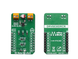
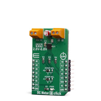
Native view of the DC Motor 11 click board.

View full image
DC Motor 11 click

DC Motor 11 click

Front and back view of the DC Motor 11 click board.

View full image

Library Description

The library contains all the necessary functions for full DC motor control.

Key functions:

  • void dcmotor11_control(uint8_t dir, uint8_t speed) - Motor Control.
  • void dcmotor11_stop() - Motor Stop.
  • uint8_t dcmotor11_getFault() - Get Fault.

Examples description

The application is composed of three sections :

  • System Initialization - Initialzes I2C module and sets INT pin as INPUT
  • Application Initialization - Initialization driver init and sets first motor settings.
  • Application Task - Waits for valid user input and executes functions based on set of valid commands.
  • Commands : '+' - Voltage (Speed) up '-' - Voltage (Speed) down 's' - Motor State - Stop/Start 'd' - Direction - Forword/Backword
void applicationTask()
{
    uint8_t dataReady_;
    char receivedData_;

    dataReady_ = UART_Rdy_Ptr( );

    if (dataReady_ != 0)
    {
        receivedData_ = UART_Rd_Ptr( );

        switch (receivedData_)
        {
            case '+' :
            {
                /* Speed increase */
                motorSpeed += 4;
                if(motorSpeed >= _DCMOTOR11_VSET_4820mV)
                {
                    mikrobus_logWrite("---- MAX SPEED ----", _LOG_LINE);
                    motorSpeed = _DCMOTOR11_VSET_4820mV;
                    dcmotor11_control(motorDir, motorSpeed);
                }
                else
                {
                    mikrobus_logWrite("---- Speed increase ----", _LOG_TEXT);
                    
                    mikrobus_logWrite(" MOTOR SPEED: ", _LOG_TEXT);
                    IntToStr(motorSpeed, demoText);
                    mikrobus_logWrite(demoText, _LOG_LINE);
                    
                    dcmotor11_control(motorDir, motorSpeed);
                }
                break;
            }
            case '-' :
            {
                /* Speed decrease */
                motorSpeed -= 4;
                if( motorSpeed < _DCMOTOR11_VSET_480mV )
                {
                    mikrobus_logWrite("---- MIN SPEED ----", _LOG_LINE);
                    motorSpeed = _DCMOTOR11_VSET_480mV;
                }
                else
                {
                    mikrobus_logWrite("---- Speed decrease ----", _LOG_TEXT);
                    
                    mikrobus_logWrite(" MOTOR SPEED: ", _LOG_TEXT);
                    IntToStr(motorSpeed, demoText);
                    mikrobus_logWrite(demoText, _LOG_LINE);
                    
                    dcmotor11_control(motorDir, motorSpeed);
                }
                break;
            }
            case 's' :
            {
                /* Stop / Start */
                if(fMotorState == 1)
                {
                     mikrobus_logWrite("---- Stop Motor!!! ----", _LOG_LINE);
                     fMotorState = 0;
                     dcmotor11_stop();
                }
                else
                {
                    mikrobus_logWrite("---- Start Motor ----", _LOG_LINE);
                    fMotorState = 1;
                    motorSpeed = _DCMOTOR11_VSET_480mV;
                    dcmotor11_control(motorDir, motorSpeed);
                }
                break;
            }
            case 'd' :
            {
                /* Direction - Forward / Backword */
                if(motorDir == 2)
                {
                     mikrobus_logWrite("---- Direction - [FORWARD] ----", _LOG_LINE);
                     motorDir = 1;
                     dcmotor11_control(motorDir, motorSpeed);
                }
                else
                {
                    mikrobus_logWrite("---- Direction - [BACKWARD] ----", _LOG_LINE);
                    motorDir = 2;
                    dcmotor11_control(motorDir, motorSpeed);
                }
                break;
            }
        }
    }
}


The full application code, and ready to use projects can be found on our LibStock page.

Other mikroE Libraries used in the example:

  • I2C
  • UART
  • Conversions

Additional notes and informations

Depending on the development board you are using, you may need USB UART clickUSB UART 2 click or RS232 click to connect to your PC, for development systems with no UART to USB interface available on the board. The terminal available in all MikroElektronika compilers, or any other terminal application of your choice, can be used to read the message.

ALSO FROM THIS AUTHOR

Signal Relay click

0

Signal Relay click can be used for ON/OFF control in various devices. It carries four ultra-small GV5-1 PCB relays from Omron and runs on a 5V power supply. Signal Relay click communicates with the target MCU over the following mikroBUS pins: AN, RST, CS and PWM.

[Learn More]

UART MUX 2 Click

0

UART MUX 2 Click is a compact add-on board that enables pseudo-multidrop RS232 transmission. This board features the MAX399, a precise CMOS analog multiplexer that allows four remote RS-232 transceivers to share a single UART from Maxim Integrated. It offers fast switching speeds with a transition time of less than 250ns and low on-resistance less than 100Ω while retains CMOS-logic input compatibility and fast switching. Channel selection is performed through a set of specific GPIO pins and possesses additional functionality such as the manual ON/OFF feature. This Click board™ is suitable for a wide range of applications, from industrial and instrumentation to a consumer, communications, data-acquisition systems, and many more.

[Learn More]

LSM303AGR Click

6

LSM303AGR click measures acceleration and magnetic field characteristics. It carries the LSM303AGR 3D accelerometer and 3D magnetometer. LSM303AGR click is designed to run on a 3.3V power supply. It communicates with the target microcontroller over I2C interface.

[Learn More]