TOP Contributors

  1. MIKROE (2752 codes)
  2. Alcides Ramos (372 codes)
  3. Shawon Shahryiar (307 codes)
  4. jm_palomino (118 codes)
  5. Bugz Bensce (90 codes)
  6. S P (73 codes)
  7. dany (71 codes)
  8. MikroBUS.NET Team (35 codes)
  9. NART SCHINACKOW (34 codes)
  10. Armstrong Subero (27 codes)

Most Downloaded

  1. Timer Calculator (139064 times)
  2. FAT32 Library (71594 times)
  3. Network Ethernet Library (56989 times)
  4. USB Device Library (47330 times)
  5. Network WiFi Library (43006 times)
  6. FT800 Library (42297 times)
  7. GSM click (29777 times)
  8. mikroSDK (27874 times)
  9. PID Library (26858 times)
  10. microSD click (26129 times)
Libstock prefers package manager

Package Manager

We strongly encourage users to use Package manager for sharing their code on Libstock website, because it boosts your efficiency and leaves the end user with no room for error. [more info]

< Back
mikroSDK Library

Buck 10 click

Rating:

5

Author: MIKROE

Last Updated: 2019-06-04

Package Version: 1.0.0.0

mikroSDK Library: 1.0.0.0

Category: Buck

Downloaded: 3330 times

Not followed.

License: MIT license  

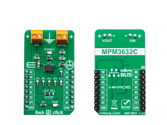
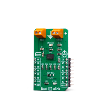
Buck 10 Click is a high-efficiency step-down converter which provides a highly regulated output voltage derived from the connected power source, rated from 4V to 18V.

No Abuse Reported

Do you want to subscribe in order to receive notifications regarding "Buck 10 click" changes.

Do you want to unsubscribe in order to stop receiving notifications regarding "Buck 10 click" changes.

Do you want to report abuse regarding "Buck 10 click".
  • mikroSDK Library 2.0.0.0
  • Comments (0)
DOWNLOAD LINK RELATED COMPILER CONTAINS
mikroBasic PRO for ARM
  • lib
  • src
  • exa
  • hlp
  • hex
  • sch
  • pcb
  • doc
mikroBasic PRO for AVR
  • lib
  • src
  • exa
  • hlp
  • hex
  • sch
  • pcb
  • doc
mikroBasic PRO for dsPIC30/33 & PIC24
  • lib
  • src
  • exa
  • hlp
  • hex
  • sch
  • pcb
  • doc
mikroBasic PRO for FT90x
  • lib
  • src
  • exa
  • hlp
  • hex
  • sch
  • pcb
  • doc
mikroBasic PRO for PIC
  • lib
  • src
  • exa
  • hlp
  • hex
  • sch
  • pcb
  • doc
mikroBasic PRO for PIC32
  • lib
  • src
  • exa
  • hlp
  • hex
  • sch
  • pcb
  • doc
mikroC PRO for ARM
  • lib
  • src
  • exa
  • hlp
  • hex
  • sch
  • pcb
  • doc
mikroC PRO for AVR
  • lib
  • src
  • exa
  • hlp
  • hex
  • sch
  • pcb
  • doc
mikroC PRO for dsPIC30/33 & PIC24
  • lib
  • src
  • exa
  • hlp
  • hex
  • sch
  • pcb
  • doc
mikroC PRO for FT90x
  • lib
  • src
  • exa
  • hlp
  • hex
  • sch
  • pcb
  • doc
mikroC PRO for PIC
  • lib
  • src
  • exa
  • hlp
  • hex
  • sch
  • pcb
  • doc
mikroC PRO for PIC32
  • lib
  • src
  • exa
  • hlp
  • hex
  • sch
  • pcb
  • doc
mikroPascal PRO for ARM
  • lib
  • src
  • exa
  • hlp
  • hex
  • sch
  • pcb
  • doc
mikroPascal PRO for AVR
  • lib
  • src
  • exa
  • hlp
  • hex
  • sch
  • pcb
  • doc
mikroPascal PRO for dsPIC30/33 & PIC24
  • lib
  • src
  • exa
  • hlp
  • hex
  • sch
  • pcb
  • doc
mikroPascal PRO for FT90x
  • lib
  • src
  • exa
  • hlp
  • hex
  • sch
  • pcb
  • doc
mikroPascal PRO for PIC
  • lib
  • src
  • exa
  • hlp
  • hex
  • sch
  • pcb
  • doc
mikroPascal PRO for PIC32
  • lib
  • src
  • exa
  • hlp
  • hex
  • sch
  • pcb
  • doc

mikroSDK Library Blog

Buck 10 click

Buck 10 click

Native view of the Buck 10 click board.

View full image
Buck 10 click

Buck 10 click

Front and back view of the Buck 10 click board.

View full image

Library Description

This library allows user to perform a control of the Buck 10 Click board. User can drive the control pin (EN) to turn ON/OFF the device and output voltage. For more details check documentation.

Key functions:

  • void buck10_gpioDriverInit(T_BUCK10_P gpioObj) - Convert ADC value to Pressure data in mBar.
  • T_BUCK10_RETVAL buck10_enable( T_BUCK10_STATE pwr_state ) - This function allows user to enable or disable the device.

Examples description

The application is composed of three sections :

  • System Initialization - Initializes PWM control pin as output and USBUART A port for logging.
  • Application Initialization - Initializes GPIO driver.
  • Application Task - (code snippet) - Turns ON the Buck 10 for 10 seconds and after that turns OFF the device and output for 10 seconds, and then repeats the all operation. Also when a device state was changed, a message will be sent to the uart terminal. Note: Input voltage recommended range - from 4V to 18V Low-side valley current limit - from 3A to 3.9A Low-side negative current limit - (-2.5A) Output voltage - 3.3V or 5V
void applicationTask()
{
    buck10_enable( _BUCK10_ENABLE );
    mikrobus_logWrite( "** Buck 10 is enabled **", _LOG_LINE );
    Delay_ms( 10000 );
    
    buck10_enable( _BUCK10_DISABLE );
    mikrobus_logWrite( "** Buck 10 is disabled **", _LOG_LINE );
    Delay_ms( 10000 );
}

Other mikroE Libraries used in the example:

  • UART

Additional notes and informations

Depending on the development board you are using, you may need USB UART clickUSB UART 2 click or RS232 click to connect to your PC, for development systems with no UART to USB interface available on the board. The terminal available in all MikroElektronika compilers, or any other terminal application of your choice, can be used to read the message.

ALSO FROM THIS AUTHOR

H-Bridge 6 click

5

H-Bridge 6 Click is a compact add-on board that contains a DC motor driver for automotive applications. This board features the VNHD7008AY, an H-bridge motor driver for automotive DC motor driving from STMicroelectronics.

[Learn More]

13DOF 2 click

5

13DOF 2 click is an advanced 13-axis motion tracking Click board, which utilizes two different sensor ICs onboard: BME680, voc, humidity, pressure and temperature sensor and BMX160, a 9-axis sensor consisting of a 3-axis, low-g accelerometer, a low power 3-axis gyroscope and a 3-axis geomagnetic sensor.

[Learn More]

NFC Tag 2 click

6

NFC Tag 2 click carries the NT3H2111 NTAG I2C energy harvesting NFC Forum Type 2 Tag with field detection pin. The click is designed to run on a 3.3V power supply only. It communicates with the target MCU over I2C interface.

[Learn More]