TOP Contributors

  1. MIKROE (2784 codes)
  2. Alcides Ramos (405 codes)
  3. Shawon Shahryiar (307 codes)
  4. jm_palomino (133 codes)
  5. Bugz Bensce (97 codes)
  6. S P (73 codes)
  7. dany (71 codes)
  8. MikroBUS.NET Team (35 codes)
  9. NART SCHINACKOW (34 codes)
  10. Armstrong Subero (27 codes)

Most Downloaded

  1. Timer Calculator (142092 times)
  2. FAT32 Library (75352 times)
  3. Network Ethernet Library (59521 times)
  4. USB Device Library (49544 times)
  5. Network WiFi Library (45336 times)
  6. FT800 Library (44956 times)
  7. GSM click (31464 times)
  8. mikroSDK (30506 times)
  9. microSD click (27825 times)
  10. PID Library (27628 times)
Libstock prefers package manager

Package Manager

We strongly encourage users to use Package manager for sharing their code on Libstock website, because it boosts your efficiency and leaves the end user with no room for error. [more info]

< Back
mikroSDK Library

Charger 9 click

Rating:

5

Author: MIKROE

Last Updated: 2019-05-27

Package Version: 1.0.0.0

mikroSDK Library: 1.0.0.0

Category: Battery Charger

Downloaded: 4553 times

Not followed.

License: MIT license  

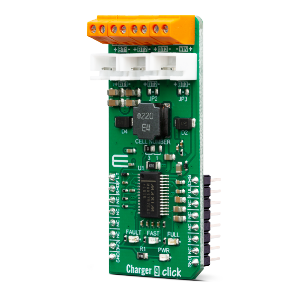
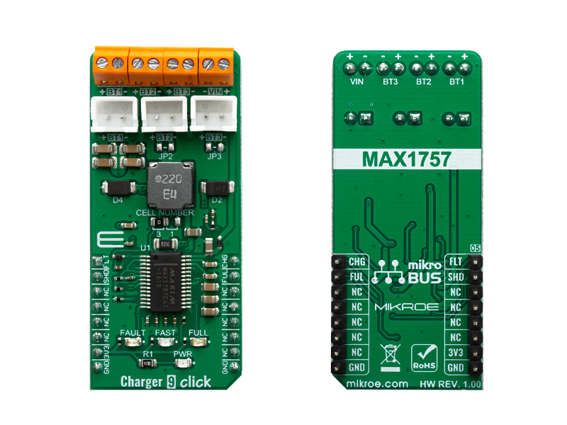
Charger 9 click is a Li-Ion (Li+, Li-Po) battery charger, capable of charging one, two or three battery cells. It is based on the MAX1757, an integrated Li+ battery charger with many features that allow safe and reliable charging.

No Abuse Reported

Do you want to subscribe in order to receive notifications regarding "Charger 9 click" changes.

Do you want to unsubscribe in order to stop receiving notifications regarding "Charger 9 click" changes.

Do you want to report abuse regarding "Charger 9 click".

  • mikroSDK Library 2.0.0.0
  • Comments (0)
DOWNLOAD LINK RELATED COMPILER CONTAINS
mikroBasic PRO for ARM
  • lib
  • src
  • exa
  • hlp
  • hex
  • sch
  • pcb
  • doc
mikroBasic PRO for AVR
  • lib
  • src
  • exa
  • hlp
  • hex
  • sch
  • pcb
  • doc
mikroBasic PRO for dsPIC30/33 & PIC24
  • lib
  • src
  • exa
  • hlp
  • hex
  • sch
  • pcb
  • doc
mikroBasic PRO for FT90x
  • lib
  • src
  • exa
  • hlp
  • hex
  • sch
  • pcb
  • doc
mikroBasic PRO for PIC
  • lib
  • src
  • exa
  • hlp
  • hex
  • sch
  • pcb
  • doc
mikroBasic PRO for PIC32
  • lib
  • src
  • exa
  • hlp
  • hex
  • sch
  • pcb
  • doc
mikroC PRO for ARM
  • lib
  • src
  • exa
  • hlp
  • hex
  • sch
  • pcb
  • doc
mikroC PRO for AVR
  • lib
  • src
  • exa
  • hlp
  • hex
  • sch
  • pcb
  • doc
mikroC PRO for dsPIC30/33 & PIC24
  • lib
  • src
  • exa
  • hlp
  • hex
  • sch
  • pcb
  • doc
mikroC PRO for FT90x
  • lib
  • src
  • exa
  • hlp
  • hex
  • sch
  • pcb
  • doc
mikroC PRO for PIC
  • lib
  • src
  • exa
  • hlp
  • hex
  • sch
  • pcb
  • doc
mikroC PRO for PIC32
  • lib
  • src
  • exa
  • hlp
  • hex
  • sch
  • pcb
  • doc
mikroPascal PRO for ARM
  • lib
  • src
  • exa
  • hlp
  • hex
  • sch
  • pcb
  • doc
mikroPascal PRO for AVR
  • lib
  • src
  • exa
  • hlp
  • hex
  • sch
  • pcb
  • doc
mikroPascal PRO for dsPIC30/33 & PIC24
  • lib
  • src
  • exa
  • hlp
  • hex
  • sch
  • pcb
  • doc
mikroPascal PRO for FT90x
  • lib
  • src
  • exa
  • hlp
  • hex
  • sch
  • pcb
  • doc
mikroPascal PRO for PIC
  • lib
  • src
  • exa
  • hlp
  • hex
  • sch
  • pcb
  • doc
mikroPascal PRO for PIC32
  • lib
  • src
  • exa
  • hlp
  • hex
  • sch
  • pcb
  • doc

mikroSDK Library Blog

Charger 9 click

Charger 9 click

Native view of the Charger 9 click board.

View full image
Charger 9 click

Charger 9 click

Front and back view of the Charger 9 click board.

View full image

Library Description

This library allows user to perform a control of the Charger 9 Click board. Also user can check the indication status from the charger to get charging state. Fault condition also can be checked. For more details check documentation.

Key functions:

  • void charger9_gpioDriverInit(T_CHARGER9_P gpioObj) - Convert ADC value to Pressure data in mBar.
  • T_CHARGER9_RETVAL charger9_enable( T_CHARGER9_STATE pwr_state ) - Convert ADC value to Voltage in mV.
  • T_CHARGER9_RETVAL charger9_faultInd( void ) - Sets max output voltage on the AN pin.

Examples description

The application is composed of three sections :

  • System Initialization - Initializes peripherals and pins.
  • Application Initialization - Initializes GPIO driver and turns OFF the charger as initial state.
  • Application Task - (code snippet) - Checks which command was sent by user and performs the selected command. Also checks the fault condition, and when fault condition is detected sends a report message to the uart terminal and turns OFF the charger. Note: When user sends a desired command to the charger, a report message will be sent to the uart terminal as indication to the user. The possible commands, for Charger 9 control, will be written to the uart terminal. The alarm sound will be generated on the determined commands: enable, disable and fault condition detecting.
void applicationTask()
{
	rx_dat = UART_Rdy_Ptr();
	
	if (rx_dat != 0)
	{
		rx_dat = UART_Rd_Ptr();
		
		switch (rx_dat)
		{
			case 'e' :
			{
				if (en_flag == _CHARGER9_DISABLE)
				{
					charger9_enable( _CHARGER9_ENABLE );
					en_flag = _CHARGER9_ENABLE;
					
					mikrobus_logWrite( "** Charger 9 is enabled **", _LOG_LINE );
					alarmOn();
				}
				else
				{
					mikrobus_logWrite( "** Charger 9 is already enabled **", _LOG_LINE );
				}
			break;
			}
			case 'd' :
			{
				if (en_flag == _CHARGER9_ENABLE)
				{
					charger9_enable( _CHARGER9_DISABLE );
					en_flag = _CHARGER9_DISABLE;

					mikrobus_logWrite( "** Charger 9 is disabled **", _LOG_LINE );
					alarmOff();
				}
				else
				{
					mikrobus_logWrite( "** Charger 9 is already disabled **", _LOG_LINE );
				}
			break;
			}
			case 's' :
			{
				charge_state = charger9_fullChargeInd();
				
				if (charge_state == _CHARGER9_IND_ACTIVE)
				{
					mikrobus_logWrite( "** Full-Charge state **", _LOG_LINE );
				}
				
				charge_state = charger9_fastChargeInd();

				if (charge_state == _CHARGER9_IND_ACTIVE)
				{
					mikrobus_logWrite( "** Fast-Charge state **", _LOG_LINE );
				}
			break;
			}
			case 'l' :
			{
				writeLegend();
			break;
			}
			default :
			{
				mikrobus_logWrite( "** Invalid command **", _LOG_LINE );
				writeLegend();
			break;
			}
		}
	}
	
	charge_state = charger9_faultInd();
	
	if (charge_state == _CHARGER9_IND_ACTIVE)
	{
		charger9_enable( _CHARGER9_DISABLE );
		en_flag = _CHARGER9_DISABLE;
		
		mikrobus_logWrite( "** Fault condition! **", _LOG_LINE );
		mikrobus_logWrite( "** Charger 9 is disabled **", _LOG_LINE );
		alarmFault();
	}
}
			

Additional Functions :

  • alarmOn - Generates an alarm sound for charger power ON.
  • alarmOff - Generates an alarm sound for charger power OFF.
  • alarmFault - Generates an alarm sound for fault condition.
  • writeLegend - Writes possible valid commands to the uart terminal.

Other mikroE Libraries used in the example:

  • Sound
  • UART

Additional notes and informations

Depending on the development board you are using, you may need USB UART clickUSB UART 2 click or RS232 click to connect to your PC, for development systems with no UART to USB interface available on the board. The terminal available in all MikroElektronika compilers, or any other terminal application of your choice, can be used to read the message.

ALSO FROM THIS AUTHOR

Vibro Motor 2 click

5

Vibro Motor 2 Click features a compact size Eccentric Rotating Mass (ERM) motor, labeled as Z4FC1B1301781 as well as DMG3420U MOSFET to drive the ERM motor, since the MCU itself cannot provide enough power for the motor driving.

[Learn More]

ADC 19 Click

0

ADC 19 Click is a compact add-on board that contains a high-performance data converter. This board features the ADC122S101, a low-power two-channel CMOS 12-bit analog-to-digital converter from Texas Instruments. This SPI configurable analog-to-digital converter (ADC) is fully specified over a sample rate range of 500ksps to 1Msps, offering high reliability and performance. The converter is based on a successive-approximation register architecture with an internal track-and-hold circuit configurable to accept one or two input signals at its input channels.

[Learn More]

Expand 4 click

5

This is a sample program that demonstrates the usage of the ST's TPIC6A595 shift register. In this example, the LED pin mask is transferred via SPI bus to the TPIC6A595 shift register and LEDs connected to D0-D7 pins are lit accordingly.

[Learn More]