TOP Contributors

  1. MIKROE (2784 codes)
  2. Alcides Ramos (405 codes)
  3. Shawon Shahryiar (307 codes)
  4. jm_palomino (133 codes)
  5. Bugz Bensce (97 codes)
  6. S P (73 codes)
  7. dany (71 codes)
  8. MikroBUS.NET Team (35 codes)
  9. NART SCHINACKOW (34 codes)
  10. Armstrong Subero (27 codes)

Most Downloaded

  1. Timer Calculator (141514 times)
  2. FAT32 Library (74401 times)
  3. Network Ethernet Library (58914 times)
  4. USB Device Library (48964 times)
  5. Network WiFi Library (44727 times)
  6. FT800 Library (44292 times)
  7. GSM click (31003 times)
  8. mikroSDK (29859 times)
  9. PID Library (27432 times)
  10. microSD click (27410 times)
Libstock prefers package manager

Package Manager

We strongly encourage users to use Package manager for sharing their code on Libstock website, because it boosts your efficiency and leaves the end user with no room for error. [more info]

< Back
mikroSDK Library

STSPIN220 click

Rating:

5

Author: MIKROE

Last Updated: 2019-05-06

Package Version: 1.0.0.0

mikroSDK Library: 1.0.0.0

Category: Stepper

Downloaded: 4633 times

Not followed.

License: MIT license  

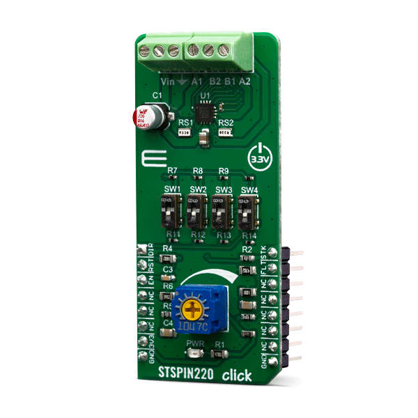
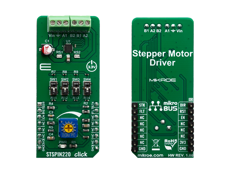
STSPIN220 click is a stepper motor driver with the PWM current control and selectable microstepping up to 256 microsteps. It is based on the STSPIN220, a low voltage stepper motor driver from STSPIN2 series.

No Abuse Reported

Do you want to subscribe in order to receive notifications regarding "STSPIN220 click" changes.

Do you want to unsubscribe in order to stop receiving notifications regarding "STSPIN220 click" changes.

Do you want to report abuse regarding "STSPIN220 click".

  • mikroSDK Library 2.0.0.0
  • Comments (0)
DOWNLOAD LINK RELATED COMPILER CONTAINS
mikroBasic PRO for ARM
  • lib
  • src
  • exa
  • hlp
  • hex
  • sch
  • pcb
  • doc
mikroBasic PRO for AVR
  • lib
  • src
  • exa
  • hlp
  • hex
  • sch
  • pcb
  • doc
mikroBasic PRO for dsPIC30/33 & PIC24
  • lib
  • src
  • exa
  • hlp
  • hex
  • sch
  • pcb
  • doc
mikroBasic PRO for FT90x
  • lib
  • src
  • exa
  • hlp
  • hex
  • sch
  • pcb
  • doc
mikroBasic PRO for PIC
  • lib
  • src
  • exa
  • hlp
  • hex
  • sch
  • pcb
  • doc
mikroBasic PRO for PIC32
  • lib
  • src
  • exa
  • hlp
  • hex
  • sch
  • pcb
  • doc
mikroC PRO for ARM
  • lib
  • src
  • exa
  • hlp
  • hex
  • sch
  • pcb
  • doc
mikroC PRO for AVR
  • lib
  • src
  • exa
  • hlp
  • hex
  • sch
  • pcb
  • doc
mikroC PRO for dsPIC30/33 & PIC24
  • lib
  • src
  • exa
  • hlp
  • hex
  • sch
  • pcb
  • doc
mikroC PRO for FT90x
  • lib
  • src
  • exa
  • hlp
  • hex
  • sch
  • pcb
  • doc
mikroC PRO for PIC
  • lib
  • src
  • exa
  • hlp
  • hex
  • sch
  • pcb
  • doc
mikroC PRO for PIC32
  • lib
  • src
  • exa
  • hlp
  • hex
  • sch
  • pcb
  • doc
mikroPascal PRO for ARM
  • lib
  • src
  • exa
  • hlp
  • hex
  • sch
  • pcb
  • doc
mikroPascal PRO for AVR
  • lib
  • src
  • exa
  • hlp
  • hex
  • sch
  • pcb
  • doc
mikroPascal PRO for dsPIC30/33 & PIC24
  • lib
  • src
  • exa
  • hlp
  • hex
  • sch
  • pcb
  • doc
mikroPascal PRO for FT90x
  • lib
  • src
  • exa
  • hlp
  • hex
  • sch
  • pcb
  • doc
mikroPascal PRO for PIC
  • lib
  • src
  • exa
  • hlp
  • hex
  • sch
  • pcb
  • doc
mikroPascal PRO for PIC32
  • lib
  • src
  • exa
  • hlp
  • hex
  • sch
  • pcb
  • doc

mikroSDK Library Blog

STSPIN220 click

STSPIN220 click

Native view of the STSPIN220 Click board.

View full image
STSPIN220 click

STSPIN220 click

Front and back view of the STSPIN220 Click board.

View full image

Library Description

Library carries everything needed for stepper motor control including speed and acceleration setup. Library is also adjustable to working on different amount of ticks per second, also speed and acceleration can be provided in float format. Buffer used for movement calculation is defined by user so this library can be adjusted for MCUs with very limited RAM resources. Check documentation for more details how to use it.

Key functions:

  • uint8_t stspin220_setSpeed( float minSpeed, float maxSpeed, float accelRatio, T_STSPIN220_OBJ obj ) - Setup motor speed.
  • uint8_t stspin220_setRoute( const uint8_t direction, uint32_t steps, T_STSPIN220_OBJ obj ) - Setup new route.
  • void stspin220_start( T_STSPIN220_OBJ obj ) - Start motor movement.

Examples description

The application is composed of the three sections :

  • System Initialization - Initializes all GPIO pins found on STSPIN220 Click and timer to 1ms interrupt.
  • Application Initialization - First segment initializes driver and stepper control. Second segment setup movement limits, maximum and minimum speed, and acceleration ratio. Third segment enables motor and setup new route which will be called from application task.
  • Application Task - (code snippet) - Sequentialy moves motor. First part of sequence executes movement until the end. Second part stop motor movement after one second and continues sequence after two seconds.
void applicationTask()
{
    stspin220_start( (T_STSPIN220_OBJ)&myStepper );
    while ( myStepper.status.running )
	{
	    stspin220_process( (T_STSPIN220_OBJ)&myStepper );
	}
    Delay_ms( 2000 );
    
    stspin220_start( (T_STSPIN220_OBJ)&myStepper );
    Delay_ms( 1000 );
    stspin220_stop( (T_STSPIN220_OBJ)&myStepper );
    Delay_ms( 2000 );
}

In addition to library function calls example carries necessay Timer ISR and Timer initialization. Check Timer initialization setings and update it according to your MCU - Timer Calculator.

Additional notes and informations

Depending on the development board you are using, you may need USB UART clickUSB UART 2 click or RS232 click to connect to your PC, for development systems with no UART to USB interface available on the board. The terminal available in all MikroElektronika compilers, or any other terminal application of your choice, can be used to read the message.

ALSO FROM THIS AUTHOR

Clock Gen 6 Click

0

Clock Gen 6 Click is a compact add-on board representing a digital oscillator solution. This board features the MIC1557, an IttyBitty CMOS RC oscillator designed to provide rail-to-rail pulses for precise time delay or frequency generation from Microchip Technology. The MIC1557 has a single threshold and trigger connection, internally connected, for astable (oscillator) operation only. It also has an enable/reset control signal routed to the RST pin of the mikroBUS™ socket, which controls the bias supply to the oscillator’s internal circuitry and optimizes power consumption used for oscillator power ON/OFF purposes. In addition, it provides the ability to select the desired frequency programmed via a digital potentiometer, the MAX5401.

[Learn More]

ADC 11 Click

0

ADC 11 Click is a compact add-on board that contains a high-performance data converter. This board features the LTC1864, a 16-bit 250ksps analog-to-digital converter from Analog Devices. With a typical supply current of only 850µA at the maximum sampling frequency, the LTC1864 is among the lowest power consumption ADCs available. After conversion, the LTC1864 goes into a low-power Sleep mode, further reducing the supply current. That’s why it can run at proper micro-power levels in applications that do not require the maximum sampling rate of the LTC1864. This Click board™ is suitable for high-speed data acquisition, low power battery-operated instrumentation, isolated and remote data acquisition, and many other applications.

[Learn More]

RTC 2 click

0

Example for RTC2 click board in mikroBUS form factor. It is a simple demonstration how to read/write date and time from DS1307 RTC (real-time clock). Date and time are read from the RTC every 10 milliseconds and printed on LCD. Communication with the board is done via I2C interface.

[Learn More]