TOP Contributors

  1. MIKROE (2663 codes)
  2. Alcides Ramos (358 codes)
  3. Shawon Shahryiar (307 codes)
  4. jm_palomino (112 codes)
  5. Chisanga Mumba (90 codes)
  6. S P (73 codes)
  7. dany (71 codes)
  8. MikroBUS.NET Team (35 codes)
  9. NART SCHINACKOW (34 codes)
  10. Armstrong Subero (27 codes)

Most Downloaded

  1. Timer Calculator (137076 times)
  2. FAT32 Library (70222 times)
  3. Network Ethernet Library (56094 times)
  4. USB Device Library (46407 times)
  5. Network WiFi Library (42028 times)
  6. FT800 Library (41372 times)
  7. GSM click (29109 times)
  8. mikroSDK (26551 times)
  9. PID Library (26487 times)
  10. microSD click (25483 times)
Libstock prefers package manager

Package Manager

We strongly encourage users to use Package manager for sharing their code on Libstock website, because it boosts your efficiency and leaves the end user with no room for error. [more info]

< Back
mikroSDK Library

3D Hall 7 click

Rating:

5

Author: MIKROE

Last Updated: 2019-06-27

Package Version: 1.0.0.0

mikroSDK Library: 1.0.0.0

Category: Magnetic

Downloaded: 2642 times

Not followed.

License: MIT license  

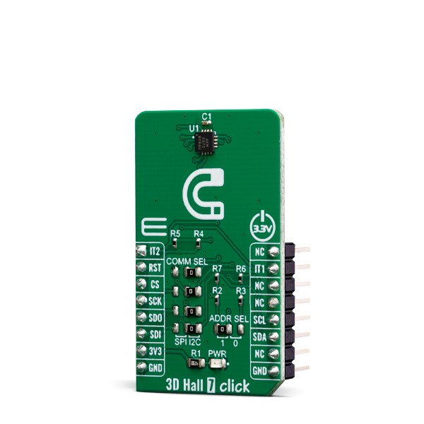
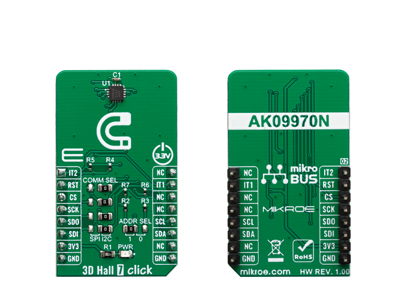
3D HALL 7 click is a very accurate, magnetic field sensing Click board, used to measure the intensity of the magnetic field across three perpendicular axes.

No Abuse Reported

Do you want to subscribe in order to receive notifications regarding "3D Hall 7 click" changes.

Do you want to unsubscribe in order to stop receiving notifications regarding "3D Hall 7 click" changes.

Do you want to report abuse regarding "3D Hall 7 click".

  • mikroSDK Library 2.0.0.0
  • Comments (0)
DOWNLOAD LINK RELATED COMPILER CONTAINS
mikroBasic PRO for ARM
  • lib
  • src
  • exa
  • hlp
  • hex
  • sch
  • pcb
  • doc
mikroBasic PRO for AVR
  • lib
  • src
  • exa
  • hlp
  • hex
  • sch
  • pcb
  • doc
mikroBasic PRO for dsPIC30/33 & PIC24
  • lib
  • src
  • exa
  • hlp
  • hex
  • sch
  • pcb
  • doc
mikroBasic PRO for FT90x
  • lib
  • src
  • exa
  • hlp
  • hex
  • sch
  • pcb
  • doc
mikroBasic PRO for PIC
  • lib
  • src
  • exa
  • hlp
  • hex
  • sch
  • pcb
  • doc
mikroBasic PRO for PIC32
  • lib
  • src
  • exa
  • hlp
  • hex
  • sch
  • pcb
  • doc
mikroC PRO for ARM
  • lib
  • src
  • exa
  • hlp
  • hex
  • sch
  • pcb
  • doc
mikroC PRO for AVR
  • lib
  • src
  • exa
  • hlp
  • hex
  • sch
  • pcb
  • doc
mikroC PRO for dsPIC30/33 & PIC24
  • lib
  • src
  • exa
  • hlp
  • hex
  • sch
  • pcb
  • doc
mikroC PRO for FT90x
  • lib
  • src
  • exa
  • hlp
  • hex
  • sch
  • pcb
  • doc
mikroC PRO for PIC
  • lib
  • src
  • exa
  • hlp
  • hex
  • sch
  • pcb
  • doc
mikroC PRO for PIC32
  • lib
  • src
  • exa
  • hlp
  • hex
  • sch
  • pcb
  • doc
mikroPascal PRO for ARM
  • lib
  • src
  • exa
  • hlp
  • hex
  • sch
  • pcb
  • doc
mikroPascal PRO for AVR
  • lib
  • src
  • exa
  • hlp
  • hex
  • sch
  • pcb
  • doc
mikroPascal PRO for dsPIC30/33 & PIC24
  • lib
  • src
  • exa
  • hlp
  • hex
  • sch
  • pcb
  • doc
mikroPascal PRO for FT90x
  • lib
  • src
  • exa
  • hlp
  • hex
  • sch
  • pcb
  • doc
mikroPascal PRO for PIC
  • lib
  • src
  • exa
  • hlp
  • hex
  • sch
  • pcb
  • doc
mikroPascal PRO for PIC32
  • lib
  • src
  • exa
  • hlp
  • hex
  • sch
  • pcb
  • doc

mikroSDK Library Blog

3D Hall 7 click

3D Hall 7 click

Native view of the 3D Hall 7 click board.

View full image
3D Hall 7 click

3D Hall 7 click

Front and back view of the 3D Hall 7 click board.

View full image

Library Description

The library initializes and defines the I2C bus or SPI bus driver and drivers that offer a choice for writing data in register and reads data from register. The library includes function for read magnetics X/Y/Z axis data, configuration device, reads interrupt states and device info(company ID and device ID).

Key functions:

  • void c3dhall7_getAxisData( T_C3DHALL7_AXIS *axis) - Get Axis data.
  • void c3dhall7_configuration(uint8_t reg, uint16_t dataIn) - Configuration function.

Examples description

The application is composed of the three sections :

  • System Initialization - Initializes I2C or SPI module and all the necessary GPIO pins.
  • Application Initialization - Initializes driver init, test communication and configuration device for measurement.
  • Application Task - Reads 3 Axis of the magnetic sensor and logs this data to USBUART every 500ms.
void applicationTask()
{
    char demoText[ 50 ];
    
    c3dhall7_getAxisData(&axis);
    
    mikrobus_logWrite("---- Measurement data of magnetic sensor ----", _LOG_LINE);
    IntToStr(axis.x, demoText);
    mikrobus_logWrite("** X axis: ", _LOG_TEXT);
    mikrobus_logWrite(demoText, _LOG_LINE);
    
    IntToStr(axis.y, demoText);
    mikrobus_logWrite("** Y axis: ", _LOG_TEXT);
    mikrobus_logWrite(demoText, _LOG_LINE);
    
    IntToStr(axis.z, demoText);
    mikrobus_logWrite("** Z axis: ", _LOG_TEXT);
    mikrobus_logWrite(demoText, _LOG_LINE);
    
    mikrobus_logWrite("---------------------------------------------", _LOG_LINE);
    Delay_ms( 500 );
}

Other mikroE Libraries used in the example:

  • SPI Library
  • I2C Library
  • UART Library
  • Conversions Library

Additional notes and informations

Depending on the development board you are using, you may need USB UART clickUSB UART 2 click or RS232 click to connect to your PC, for development systems with no UART to USB interface available on the board. The terminal available in all MikroElektronika compilers, or any other terminal application of your choice, can be used to read the message.

ALSO FROM THIS AUTHOR

DIGI POT 6 click

0

DIGI POT 6 Click features the MCP41HVX1 family of devices which have dual power rails (analog and digital). The analog power rail allows high voltage on the resistor network terminal pins.

[Learn More]

LED Driver 13 click

0

LED Driver 13 Click is a compact add-on board that simplifies the control of multiple LEDs. This board features the A80604-1, a 4-channel LED driver designed at a switching frequency of 400kHz that provides 150mA per channel from Allegro Microsystems. It is powered by an external power supply in the range of 6V to 18V, providing an output voltage of approximately 26V, which is used to power LEDs connected to LED channels. On the logical side, this board uses both 3V3 and 5V with mikroBUS™ power rails and communicates with the MCU via GPIO pins. In addition, the user is given the option of analog or digital LED dimming selection, using a PWM pin from the mikroBUS™ socket or via an onboard potentiometer/external PWM signal.

[Learn More]

Stepper 8 click

5

Stepper 8 Click is Click board based on TC78H670FT from Toshiba, a clock-in and serial controlled Bipolar Stepping Motor Driver which can drive a 128 micro-stepping motor with a power supply ranging from 2.5V to 16V for wide range of applications includes USB-powered, battery-powered, and standard 9-12V system devices.

[Learn More]