TOP Contributors

  1. MIKROE (2784 codes)
  2. Alcides Ramos (387 codes)
  3. Shawon Shahryiar (307 codes)
  4. jm_palomino (119 codes)
  5. Bugz Bensce (97 codes)
  6. S P (73 codes)
  7. dany (71 codes)
  8. MikroBUS.NET Team (35 codes)
  9. NART SCHINACKOW (34 codes)
  10. Armstrong Subero (27 codes)

Most Downloaded

  1. Timer Calculator (140131 times)
  2. FAT32 Library (72525 times)
  3. Network Ethernet Library (57599 times)
  4. USB Device Library (47918 times)
  5. Network WiFi Library (43480 times)
  6. FT800 Library (42895 times)
  7. GSM click (30115 times)
  8. mikroSDK (28618 times)
  9. PID Library (27042 times)
  10. microSD click (26526 times)
Libstock prefers package manager

Package Manager

We strongly encourage users to use Package manager for sharing their code on Libstock website, because it boosts your efficiency and leaves the end user with no room for error. [more info]

< Back
mikroSDK Library

DMX click

Rating:

5

Author: MIKROE

Last Updated: 2020-06-03

Package Version: 1.0.0.0

mikroSDK Library: 1.0.0.0

Category: DMX

Downloaded: 2636 times

Not followed.

License: MIT license  

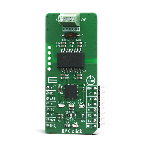
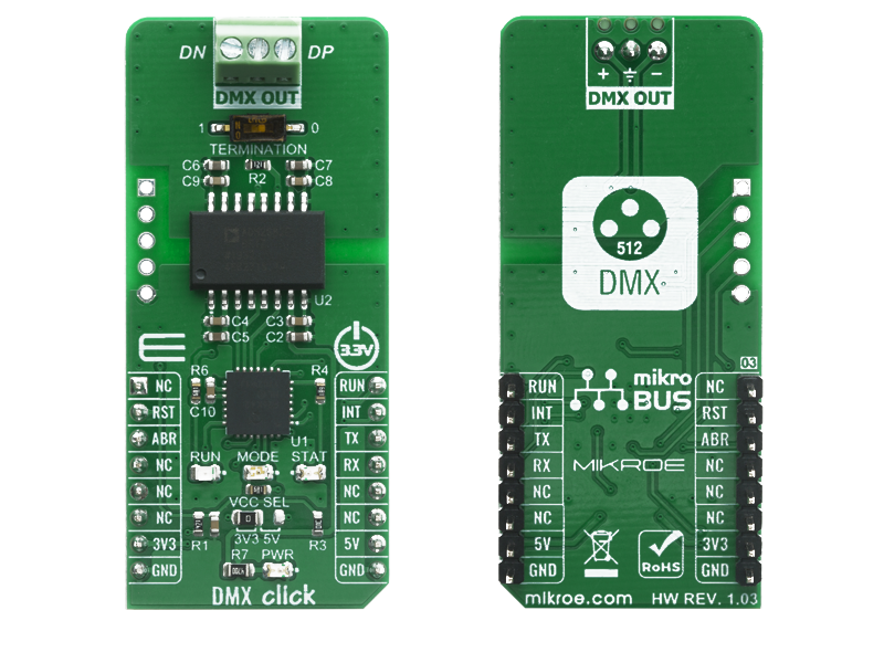
DMX Click is a device used to establish communication between the MCU and equipment that uses the DMX512-A communication protocol.

No Abuse Reported

Do you want to subscribe in order to receive notifications regarding "DMX click" changes.

Do you want to unsubscribe in order to stop receiving notifications regarding "DMX click" changes.

Do you want to report abuse regarding "DMX click".

  • mikroSDK Library 2.0.0.0
  • Comments (0)
DOWNLOAD LINK RELATED COMPILER CONTAINS
mikroBasic PRO for ARM
  • lib
  • src
  • exa
  • hlp
  • hex
  • sch
  • pcb
  • doc
mikroBasic PRO for AVR
  • lib
  • src
  • exa
  • hlp
  • hex
  • sch
  • pcb
  • doc
mikroBasic PRO for dsPIC30/33 & PIC24
  • lib
  • src
  • exa
  • hlp
  • hex
  • sch
  • pcb
  • doc
mikroBasic PRO for FT90x
  • lib
  • src
  • exa
  • hlp
  • hex
  • sch
  • pcb
  • doc
mikroBasic PRO for PIC
  • lib
  • src
  • exa
  • hlp
  • hex
  • sch
  • pcb
  • doc
mikroBasic PRO for PIC32
  • lib
  • src
  • exa
  • hlp
  • hex
  • sch
  • pcb
  • doc
mikroC PRO for ARM
  • lib
  • src
  • exa
  • hlp
  • hex
  • sch
  • pcb
  • doc
mikroC PRO for AVR
  • lib
  • src
  • exa
  • hlp
  • hex
  • sch
  • pcb
  • doc
mikroC PRO for dsPIC30/33 & PIC24
  • lib
  • src
  • exa
  • hlp
  • hex
  • sch
  • pcb
  • doc
mikroC PRO for FT90x
  • lib
  • src
  • exa
  • hlp
  • hex
  • sch
  • pcb
  • doc
mikroC PRO for PIC
  • lib
  • src
  • exa
  • hlp
  • hex
  • sch
  • pcb
  • doc
mikroC PRO for PIC32
  • lib
  • src
  • exa
  • hlp
  • hex
  • sch
  • pcb
  • doc
mikroPascal PRO for ARM
  • lib
  • src
  • exa
  • hlp
  • hex
  • sch
  • pcb
  • doc
mikroPascal PRO for AVR
  • lib
  • src
  • exa
  • hlp
  • hex
  • sch
  • pcb
  • doc
mikroPascal PRO for dsPIC30/33 & PIC24
  • lib
  • src
  • exa
  • hlp
  • hex
  • sch
  • pcb
  • doc
mikroPascal PRO for FT90x
  • lib
  • src
  • exa
  • hlp
  • hex
  • sch
  • pcb
  • doc
mikroPascal PRO for PIC
  • lib
  • src
  • exa
  • hlp
  • hex
  • sch
  • pcb
  • doc
mikroPascal PRO for PIC32
  • lib
  • src
  • exa
  • hlp
  • hex
  • sch
  • pcb
  • doc

mikroSDK Library Blog

DMX Click

DMX Click

Native view of the DMX Click board.

View full image
DMX Click

DMX Click

Front and back view of the DMX Click board.

View full image

Library Description

This library offers a choice to control stage lighting and effects. One master device can control one, two, or more slave devices. User can determine length of the DMX frame, speed of the DMX frame transfer, data length, start address, interrupt duration. Any DMX slave device (DMX Click board, RGB reflector) is determined by start address and data length. This data can consist of the, for example, color selection, light intensity, and many different effects. Master executes the DMX frame transfer, '0' always be transfered first, and slave receives data from the sent frame starting from the determined start address, '0' always be received first. This is a excellent solution to control stage lighting on the easy, simple and fast way. For more details check documentation.

Key functions:

  • void dmx_send_cmd( uint8_t *cmd, uint16_t cmd_len ) - This function sends a command to the DMX device.
  • void dmx_default_handler( void ( *handler )( uint8_t*, uint16_t*, uint8_t* ) ) - This function sets handler on the function which should be performed, for example function for the results logging.
  • void dmx_run( uint8_t run_mode ) - This function allows user to put device in config or run mode.

Examples description

The application is composed of three sections :

  • System Initialization - Initializes peripherals and pins.
  • Application Initialization - Initializes UART serial interface and executes a device configuration and mode setting. In our example the device is configured as master and allows 5 data bytes transfer starting from the address 8. DMX frame length is 15, starting from 0, and range can be from 1 to 512. Start address can be from 1 to 512 also. @FTMR,nnn - determines the delay between two DMX frame, range is from 000 to 007 (from 20ms to 160ms). @ITMR,nnn - determines the duration of the interrupt signal, range is from 000 to 007 (from 0.1ms to 1.28ms).
  • Application Task - (code snippet) - When device was configured as master, user can enter the desired 5 data bytes, that will be transfered to the slave every 140ms. When device was configured as slave, the device will receive 5 data bytes from the master, transfered from the address 8 to address 12, every 140ms (in this example). Note : RUN LED - DMX frame transfer indication STAT LED - interrupt indication MODE LED - indicates the device mode, when is set the device was configured as master, and when is reset the device was configured as slave.
void application_task( )
{
    if ( device_mode == DMX_SLAVE )
    {
        process( );
    }
    else if ( master_mode == DMX_MASTER_USER_CTRL )
    {
        uint8_t cmd_check;
        uint8_t tx_buff[ 6 ] = { 0 };

        mikrobus_logWrite( "> CH1 - light [0-255]: ", _LOG_TEXT );
        tx_buff[ 0 ] = enter_cmd( );

        mikrobus_logWrite( "> CH2 - red [0-255]: ", _LOG_TEXT );
        tx_buff[ 1 ] = enter_cmd( );

        mikrobus_logWrite( "> CH3 - green [0-255]: ", _LOG_TEXT );
        tx_buff[ 2 ] = enter_cmd( );

        mikrobus_logWrite( "> CH4 - blue [0-255]: ", _LOG_TEXT );
        tx_buff[ 3 ] = enter_cmd( );

        mikrobus_logWrite( "> CH5 - strobe [1-255]: ", _LOG_TEXT );
        tx_buff[ 4 ] = enter_cmd( );

        mikrobus_logWrite( "> CH6 - change colores [1-255]: ", _LOG_TEXT );
        tx_buff[ 5 ] = enter_cmd( );

        dmx_send_cmd( &tx_buff[ 0 ], 6 );
        cmd_check = dmx_check_int( );

        while ( cmd_check == DMX_INT_INACTIVE )
        {
            cmd_check = dmx_check_int( );
        }

        mikrobus_logWrite( "> command sent", _LOG_LINE );
        mikrobus_logWrite( "************************************", _LOG_LINE );
    }
    else
    {
        application_demo( );
    }
}


Other mikroE Libraries used in the example:

  • Conversions
  • C_String
  • UART

Additional notes and informations

Depending on the development board you are using, you may need USB UART clickUSB UART 2 click or RS232 click to connect to your PC, for development systems with no UART to USB interface available on the board. The terminal available in all MikroElektronika compilers, or any other terminal application of your choice, can be used to read the message.

ALSO FROM THIS AUTHOR

Radiation click

5

Radiation Click is a Click boardâ„¢ based on BG51 radiation sensor from Teviso Sensor Technologies. The function of the BG51 radiation sensor is based on an array of customized PIN diodes.

[Learn More]

SRAM click

6

SRAM click lets you add 1 Mbit of additional SRAM memory to your devices, via the 23LC1024 chip. The board communicates with the target MCU through the mikroBUS SPI interface (MISO, MOSI, SCK, CS). SRAM click is designed to use either a 3.3V or 5V power supply.

[Learn More]

ML Vibro Sens Click

0

ML Vibro Sens Click is a compact add-on board for motion sensing and vibration analysis. This board features the FXLS8974CF, a 3-axis low-g 12-bit digital accelerometer from NXP designed for precise motion detection and data collection. This Click board™ represents a machine learning training tool that communicates with the host MCU over an I2C interface, with selectable addresses and dual operating modes for interrupt signaling or motion detection. It features two DC motors - a balanced motor for generating steady baseline vibrations and an unbalanced motor for customizable vibration patterns controlled via PWM or PDM signals.

[Learn More]