TOP Contributors

  1. MIKROE (2784 codes)
  2. Alcides Ramos (405 codes)
  3. Shawon Shahryiar (307 codes)
  4. jm_palomino (133 codes)
  5. Bugz Bensce (97 codes)
  6. S P (73 codes)
  7. dany (71 codes)
  8. MikroBUS.NET Team (35 codes)
  9. NART SCHINACKOW (34 codes)
  10. Armstrong Subero (27 codes)

Most Downloaded

  1. Timer Calculator (141241 times)
  2. FAT32 Library (74041 times)
  3. Network Ethernet Library (58675 times)
  4. USB Device Library (48786 times)
  5. Network WiFi Library (44491 times)
  6. FT800 Library (44035 times)
  7. GSM click (30784 times)
  8. mikroSDK (29625 times)
  9. PID Library (27347 times)
  10. microSD click (27232 times)
Libstock prefers package manager

Package Manager

We strongly encourage users to use Package manager for sharing their code on Libstock website, because it boosts your efficiency and leaves the end user with no room for error. [more info]

< Back
mikroSDK Library

Balancer 3 click

Rating:

5

Author: MIKROE

Last Updated: 2019-09-11

Package Version: 1.0.0.0

mikroSDK Library: 1.0.0.0

Category: Battery Charger

Downloaded: 3705 times

Not followed.

License: MIT license  

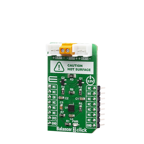
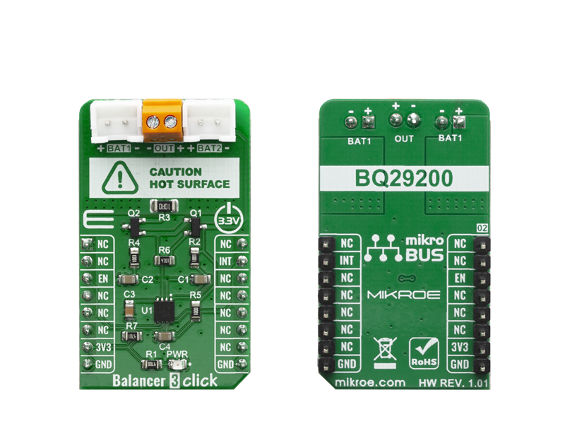
Balancer 3 Click is overvoltage protection device for 2-series cell lithium-ion battery packs that incorporates a high-accuracy precision overvoltage detection circuit and automatic cell imbalance correction.

No Abuse Reported

Do you want to subscribe in order to receive notifications regarding "Balancer 3 click" changes.

Do you want to unsubscribe in order to stop receiving notifications regarding "Balancer 3 click" changes.

Do you want to report abuse regarding "Balancer 3 click".

  • mikroSDK Library 2.0.0.0
  • Comments (0)
DOWNLOAD LINK RELATED COMPILER CONTAINS
mikroBasic PRO for ARM
  • lib
  • src
  • exa
  • hlp
  • hex
  • sch
  • pcb
  • doc
mikroBasic PRO for AVR
  • lib
  • src
  • exa
  • hlp
  • hex
  • sch
  • pcb
  • doc
mikroBasic PRO for dsPIC30/33 & PIC24
  • lib
  • src
  • exa
  • hlp
  • hex
  • sch
  • pcb
  • doc
mikroBasic PRO for FT90x
  • lib
  • src
  • exa
  • hlp
  • hex
  • sch
  • pcb
  • doc
mikroBasic PRO for PIC
  • lib
  • src
  • exa
  • hlp
  • hex
  • sch
  • pcb
  • doc
mikroBasic PRO for PIC32
  • lib
  • src
  • exa
  • hlp
  • hex
  • sch
  • pcb
  • doc
mikroC PRO for ARM
  • lib
  • src
  • exa
  • hlp
  • hex
  • sch
  • pcb
  • doc
mikroC PRO for AVR
  • lib
  • src
  • exa
  • hlp
  • hex
  • sch
  • pcb
  • doc
mikroC PRO for dsPIC30/33 & PIC24
  • lib
  • src
  • exa
  • hlp
  • hex
  • sch
  • pcb
  • doc
mikroC PRO for FT90x
  • lib
  • src
  • exa
  • hlp
  • hex
  • sch
  • pcb
  • doc
mikroC PRO for PIC
  • lib
  • src
  • exa
  • hlp
  • hex
  • sch
  • pcb
  • doc
mikroC PRO for PIC32
  • lib
  • src
  • exa
  • hlp
  • hex
  • sch
  • pcb
  • doc
mikroPascal PRO for ARM
  • lib
  • src
  • exa
  • hlp
  • hex
  • sch
  • pcb
  • doc
mikroPascal PRO for AVR
  • lib
  • src
  • exa
  • hlp
  • hex
  • sch
  • pcb
  • doc
mikroPascal PRO for dsPIC30/33 & PIC24
  • lib
  • src
  • exa
  • hlp
  • hex
  • sch
  • pcb
  • doc
mikroPascal PRO for FT90x
  • lib
  • src
  • exa
  • hlp
  • hex
  • sch
  • pcb
  • doc
mikroPascal PRO for PIC
  • lib
  • src
  • exa
  • hlp
  • hex
  • sch
  • pcb
  • doc
mikroPascal PRO for PIC32
  • lib
  • src
  • exa
  • hlp
  • hex
  • sch
  • pcb
  • doc

mikroSDK Library Blog

Balancer 3 Click

Balancer 3 Click

Native view of the Balancer 3 Click board.

View full image
Balancer 3 Click

Balancer 3 Click

Front and back view of the Balancer 3 Click board.

View full image

Library Description

This library allows user to perform a control of the Balancer 3 Click board and to check the Overvoltage condition status. This click also can be used for power supply with the voltage range from 6V to 8.4V. For more details check documentation.

Key functions:

  • void balancer3_gpioDriverInit( T_BALANCER3_P gpioObj ) - This function initializes GPIO driver.
  • void balancer3_enable_cell_balance( uint8_t state ) - This function allows user to enable or disable Cell Balance (cell mismatch correction circuitry).
  • uint8_t balancer3_check_overvoltage_cond( void ) - This function checks the Overvoltage condition.

Examples description

The application is composed of three sections :

  • System Initialization - Initializes peripherals and pins.
  • Application Initialization - Initializes GPIO driver and sets the time interval variable (time_inter) to the 0, which is used for OV condition message logging.
  • Application Task - (code snippet) - Allows user to enter a commands that can enable or disable cell balance and check the overvoltage condition. When OV condition is not detected, the status message will be sent after every 8 seconds. When OV condition is detected, the status message will be sent after every 2 seconds. Press '0' when you want to disable cell balance. Press '1' when you want to enable cell balance. Press '2' when you want to check the OV condition status immediately. Note : The voltage of each cell in a 2-series cell battery pack is compared to an internal reference voltage. If either cell reaches an overvoltage condition, the Balancer 3 click starts a timer that provides a delay proportional to the capacitance on the CD pin, in our example it's about 2 seconds. Upon expiration of the internal timer, the OV condition will be detected. If enabled, the Balancer 3 click performs automatic cell imbalance correction where the two cells are automatically corrected for voltage imbalance by loading the cell with the higher charge voltage with a small balancing current. When the cells are measured to be equal within nominally 0 mV, the load current is removed. It will be re-applied if the imbalance exceeds nominally 30 mV. The cell mismatch correction circuitry is controlled by the user.
void applicationTask()
{
    rx_dat = UART_Rdy_Ptr();
    
    if (rx_dat != _RX_NOT_READY)
    {
        rx_dat = UART_Rd_Ptr();
        
        switch (rx_dat)
        {
            case '0' :
            {
                balancer3_enable_cell_balance( _BALANCER3_CELL_BALANCE_DIS );
                mikrobus_logWrite( "* Cell balance is disabled *", _LOG_LINE );
            break;
            }
            case '1' :
            {
                balancer3_enable_cell_balance( _BALANCER3_CELL_BALANCE_EN );
                mikrobus_logWrite( "* Cell balance is enabled *", _LOG_LINE );
            break;
            }
            case '2' :
            {
                time_inter = 8000;
            break;
            }
            default :
            {
            break;
            }
        }
    }
    
    ov_cond = balancer3_check_overvoltage_cond();
    
    if ((time_inter == 8000) || (ov_cond == _BALANCER3_OV_COND_DETECTED))
    {
        if (ov_cond == _BALANCER3_OV_COND_NOT_DETECTED)
        {
            mikrobus_logWrite( "* Overvoltage condition is not detected *", _LOG_LINE );
            time_inter = 0;
        }
        else if (time_inter > 2000)
        {
            mikrobus_logWrite( "* Overvoltage condition is detected *", _LOG_LINE );
            time_inter = 0;
        }
        else
        {
            time_inter++;
        }
    }
    else
    {
        time_inter++;
    }
    
    Delay_ms( 1 );
}

Other mikroE Libraries used in the example:

  • UART

Additional notes and informations

Depending on the development board you are using, you may need USB UART clickUSB UART 2 click or RS232 click to connect to your PC, for development systems with no UART to USB interface available on the board. The terminal available in all MikroElektronika compilers, or any other terminal application of your choice, can be used to read the message.

ALSO FROM THIS AUTHOR

LTE Cat.1-US click

5

LTE Cat.1-US click is a Click board based on Thales Cinterion ELS61 wireless module that delivers highly efficient Cat 1 LTE connectivity for M2M IoT solutions offering seamless fall back to 2G and 3G networks.

[Learn More]

RS485 Isolator 4 Click

0

RS485 Isolator 4 Click is a compact add-on board designed for robust RS-485 and RS-422 half-duplex communication with galvanic isolation. This board features the ISO1450, a 5kVRMS isolated RS-485 transceiver from Texas Instruments. The ISO1450 supports data rates up to 50Mbps and features advanced protection against electrostatic discharge (ESD) and electrical fast transients (EFT), ensuring reliable long-distance communication in industrial environments. It operates over a wide supply voltage range (3V to 5.5V), offering failsafe protection against open, short, and idle bus states.

[Learn More]

Surface Temp click

5

The Surface Temp Click is a Click board equipped with the ADT7420, high accuracy digital temperature sensor offering breakthrough performance over a wide industrial range. Surface Temp Click is supported by a mikroSDK compliant library, which includes functions that simplify software development.

[Learn More]