TOP Contributors

  1. MIKROE (2762 codes)
  2. Alcides Ramos (374 codes)
  3. Shawon Shahryiar (307 codes)
  4. jm_palomino (118 codes)
  5. Bugz Bensce (90 codes)
  6. S P (73 codes)
  7. dany (71 codes)
  8. MikroBUS.NET Team (35 codes)
  9. NART SCHINACKOW (34 codes)
  10. Armstrong Subero (27 codes)

Most Downloaded

  1. Timer Calculator (139248 times)
  2. FAT32 Library (71743 times)
  3. Network Ethernet Library (57115 times)
  4. USB Device Library (47428 times)
  5. Network WiFi Library (43082 times)
  6. FT800 Library (42403 times)
  7. GSM click (29835 times)
  8. mikroSDK (28073 times)
  9. PID Library (26885 times)
  10. microSD click (26198 times)
Libstock prefers package manager

Package Manager

We strongly encourage users to use Package manager for sharing their code on Libstock website, because it boosts your efficiency and leaves the end user with no room for error. [more info]

< Back
mikroSDK Library

RS232 SPI click

Rating:

5

Author: MIKROE

Last Updated: 2020-01-20

Package Version: 1.0.0.0

mikroSDK Library: 1.0.0.0

Category: RS232

Downloaded: 3019 times

Not followed.

License: MIT license  

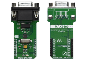
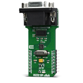
RS232 SPI click is based around the MAX3100, a universal universal asynchronous receiver transmitter (UART) - the first UART specifically optimized for small microcontroller-based systems, from Maxim Integrated.

No Abuse Reported

Do you want to subscribe in order to receive notifications regarding "RS232 SPI click" changes.

Do you want to unsubscribe in order to stop receiving notifications regarding "RS232 SPI click" changes.

Do you want to report abuse regarding "RS232 SPI click".
  • mikroSDK Library 2.0.0.0
  • Comments (0)
DOWNLOAD LINK RELATED COMPILER CONTAINS
mikroBasic PRO for ARM
  • lib
  • src
  • exa
  • hlp
  • hex
  • sch
  • pcb
  • doc
mikroBasic PRO for AVR
  • lib
  • src
  • exa
  • hlp
  • hex
  • sch
  • pcb
  • doc
mikroBasic PRO for dsPIC30/33 & PIC24
  • lib
  • src
  • exa
  • hlp
  • hex
  • sch
  • pcb
  • doc
mikroBasic PRO for FT90x
  • lib
  • src
  • exa
  • hlp
  • hex
  • sch
  • pcb
  • doc
mikroBasic PRO for PIC
  • lib
  • src
  • exa
  • hlp
  • hex
  • sch
  • pcb
  • doc
mikroBasic PRO for PIC32
  • lib
  • src
  • exa
  • hlp
  • hex
  • sch
  • pcb
  • doc
mikroC PRO for ARM
  • lib
  • src
  • exa
  • hlp
  • hex
  • sch
  • pcb
  • doc
mikroC PRO for AVR
  • lib
  • src
  • exa
  • hlp
  • hex
  • sch
  • pcb
  • doc
mikroC PRO for dsPIC30/33 & PIC24
  • lib
  • src
  • exa
  • hlp
  • hex
  • sch
  • pcb
  • doc
mikroC PRO for FT90x
  • lib
  • src
  • exa
  • hlp
  • hex
  • sch
  • pcb
  • doc
mikroC PRO for PIC
  • lib
  • src
  • exa
  • hlp
  • hex
  • sch
  • pcb
  • doc
mikroC PRO for PIC32
  • lib
  • src
  • exa
  • hlp
  • hex
  • sch
  • pcb
  • doc
mikroPascal PRO for ARM
  • lib
  • src
  • exa
  • hlp
  • hex
  • sch
  • pcb
  • doc
mikroPascal PRO for AVR
  • lib
  • src
  • exa
  • hlp
  • hex
  • sch
  • pcb
  • doc
mikroPascal PRO for dsPIC30/33 & PIC24
  • lib
  • src
  • exa
  • hlp
  • hex
  • sch
  • pcb
  • doc
mikroPascal PRO for FT90x
  • lib
  • src
  • exa
  • hlp
  • hex
  • sch
  • pcb
  • doc
mikroPascal PRO for PIC
  • lib
  • src
  • exa
  • hlp
  • hex
  • sch
  • pcb
  • doc
mikroPascal PRO for PIC32
  • lib
  • src
  • exa
  • hlp
  • hex
  • sch
  • pcb
  • doc

mikroSDK Library Blog

RS232 SPI click

RS232 SPI click

Native view of the RS232 SPI click board.

View full image
RS232 SPI click

RS232 SPI click

Front and back view of the RS232 SPI click board.

View full image

Library Description

The library covers all the necessary functions that enables the usage of the RS232 SPI click board. User can send or receive data, check if data is ready or if tx line is busy, it is possible to change baud rate and to turn the device on or off.

Key functions:

  • uint8_t rs232spi_dataRead() - Function is used to read data from the receive register.
  • uint16_t rs232spi_dataReady() - Function is used to check if there is availavle data for reading.
  • void rs232spi_dataWrite( uint8_t wrData ) - Function is used to write into the transmit-buffer register.

Examples description

The application is composed of three sections :

  • System Initialization - Initializes SPI and LOG structures, sets RST pin as output and INT pin as input.
  • Application Initialization - Initialization driver enables SPI, sets up the device and starts write log.
  • Application Task - (code snippet) This example demonstrates the use of RS232 SPI click board by sending or receveing the message.
void applicationTask()
{
    uint8_t tmp;
    char rec;
    uint8_t mode = RS232SPI_WRITE_MODE;

    if ( mode == RS232SPI_READ_MODE )
    {
        // RECEIVER - UART polling
        if ( rs232spi_dataReady() != 0 )
        {
            rec = rs232spi_transfer( _RS232SPI_CMD_READ_DATA );
            mikrobus_logWrite( &rec, _LOG_BYTE );
        }
    }
    else if ( mode == RS232SPI_WRITE_MODE )
    {
        // TRANSMITER - TX each 2 sec
        for ( tmp = 0; tmp < 9; tmp++ )
        {
            rs232spi_dataWrite( MESSAGE_DATA[ tmp ] );
            if ( tmp < 6 )
            {
                Delay_ms( 100 );
            }
        }
        Delay_ms( 2000 );
    }
}

Other mikroE Libraries used in the example:

  • SPI
  • UART
  • Conversions

Additional notes and informations

Depending on the development board you are using, you may need USB UART clickUSB UART 2 click or RS232 click to connect to your PC, for development systems with no UART to USB interface available on the board. The terminal available in all MikroElektronika compilers, or any other terminal application of your choice, can be used to read the message.

ALSO FROM THIS AUTHOR

Buggy example

1

This example demonstrates wireless Buggy control, using clicker2 for STM32/PIC32/PIC18FJ/FT900, BLE-P click board and Android smart phone.

[Learn More]

FTDI click - Example

0

This is demonstration project how FTDI click can be used to control slave microcontroller via I2C. Lower nibble of slave address is masked which enables the master to address slave using eight different addresses. Currently four addresses are implemented for different functionality.

[Learn More]

LDC 2 Click

0

LDC 2 Click is a compact add-on board that measures inductance change which a conductive target causes when it moves into the inductor's AC magnetic field. This board features the LDC1041, inductance-to-digital converter (LDC) for inductive sensing solutions from Texas Instruments.

[Learn More]