TOP Contributors

  1. MIKROE (2762 codes)
  2. Alcides Ramos (374 codes)
  3. Shawon Shahryiar (307 codes)
  4. jm_palomino (118 codes)
  5. Bugz Bensce (90 codes)
  6. S P (73 codes)
  7. dany (71 codes)
  8. MikroBUS.NET Team (35 codes)
  9. NART SCHINACKOW (34 codes)
  10. Armstrong Subero (27 codes)

Most Downloaded

  1. Timer Calculator (139250 times)
  2. FAT32 Library (71747 times)
  3. Network Ethernet Library (57120 times)
  4. USB Device Library (47430 times)
  5. Network WiFi Library (43082 times)
  6. FT800 Library (42403 times)
  7. GSM click (29835 times)
  8. mikroSDK (28074 times)
  9. PID Library (26885 times)
  10. microSD click (26198 times)
Libstock prefers package manager

Package Manager

We strongly encourage users to use Package manager for sharing their code on Libstock website, because it boosts your efficiency and leaves the end user with no room for error. [more info]

< Back
mikroSDK Library

6DOF IMU 9 click

Rating:

5

Author: MIKROE

Last Updated: 2019-11-08

Package Version: 1.0.0.0

mikroSDK Library: 1.0.0.0

Category: Motion

Downloaded: 2629 times

Not followed.

License: MIT license  

The 6DOF IMU 9 Click is a Click boardâ„¢ which features the IAM-20680, a 6-axis MotionTracking device that combines a 3-axis gyroscope and a 3-axis accelerometer, from TDK InvenSense.

No Abuse Reported

Do you want to subscribe in order to receive notifications regarding "6DOF IMU 9 click" changes.

Do you want to unsubscribe in order to stop receiving notifications regarding "6DOF IMU 9 click" changes.

Do you want to report abuse regarding "6DOF IMU 9 click".
  • mikroSDK Library 2.0.0.0
  • Comments (0)
DOWNLOAD LINK RELATED COMPILER CONTAINS
mikroBasic PRO for ARM
  • lib
  • src
  • exa
  • hlp
  • hex
  • sch
  • pcb
  • doc
mikroBasic PRO for AVR
  • lib
  • src
  • exa
  • hlp
  • hex
  • sch
  • pcb
  • doc
mikroBasic PRO for dsPIC30/33 & PIC24
  • lib
  • src
  • exa
  • hlp
  • hex
  • sch
  • pcb
  • doc
mikroBasic PRO for FT90x
  • lib
  • src
  • exa
  • hlp
  • hex
  • sch
  • pcb
  • doc
mikroBasic PRO for PIC
  • lib
  • src
  • exa
  • hlp
  • hex
  • sch
  • pcb
  • doc
mikroBasic PRO for PIC32
  • lib
  • src
  • exa
  • hlp
  • hex
  • sch
  • pcb
  • doc
mikroC PRO for ARM
  • lib
  • src
  • exa
  • hlp
  • hex
  • sch
  • pcb
  • doc
mikroC PRO for AVR
  • lib
  • src
  • exa
  • hlp
  • hex
  • sch
  • pcb
  • doc
mikroC PRO for dsPIC30/33 & PIC24
  • lib
  • src
  • exa
  • hlp
  • hex
  • sch
  • pcb
  • doc
mikroC PRO for FT90x
  • lib
  • src
  • exa
  • hlp
  • hex
  • sch
  • pcb
  • doc
mikroC PRO for PIC
  • lib
  • src
  • exa
  • hlp
  • hex
  • sch
  • pcb
  • doc
mikroC PRO for PIC32
  • lib
  • src
  • exa
  • hlp
  • hex
  • sch
  • pcb
  • doc
mikroPascal PRO for ARM
  • lib
  • src
  • exa
  • hlp
  • hex
  • sch
  • pcb
  • doc
mikroPascal PRO for AVR
  • lib
  • src
  • exa
  • hlp
  • hex
  • sch
  • pcb
  • doc
mikroPascal PRO for dsPIC30/33 & PIC24
  • lib
  • src
  • exa
  • hlp
  • hex
  • sch
  • pcb
  • doc
mikroPascal PRO for FT90x
  • lib
  • src
  • exa
  • hlp
  • hex
  • sch
  • pcb
  • doc
mikroPascal PRO for PIC
  • lib
  • src
  • exa
  • hlp
  • hex
  • sch
  • pcb
  • doc
mikroPascal PRO for PIC32
  • lib
  • src
  • exa
  • hlp
  • hex
  • sch
  • pcb
  • doc

mikroSDK Library Blog

6DOF IMU 9 click

6DOF IMU 9 click

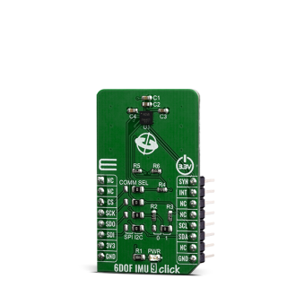
Native view of the 6DOF IMU 9 click board.

View full image
6DOF IMU 9 click

6DOF IMU 9 click

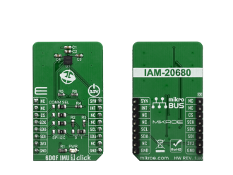
Front and back view of the ... board.

View full image

Library Description

The library covers all the necessary functions to control 6DOF IMU 9 click board. Library performs a standard I2C or SPI interface communication.

Key functions:

  • void c6dofimu9_get_accel_data( int16_t *p_accel_x, int16_t *p_accel_y, int16_t *p_accel_z ) - Read Accel X-axis, Y-axis and Z-axis axis function.
  • void c6dofimu9_get_gyro_data( int16_t *p_gyro_x, int16_t *p_gyro_y, int16_t *p_gyro_z ) - Read Gyro X-axis, Y-axis and Z-axis axis function.

Examples description

The application is composed of three sections :

  • System Initialization - Initializes I2C or SPI and start to write log.
  • Application Initialization - Initialization driver enables - I2C or SPI, check device ID, configure accelerometer and gyroscope, also write log.
  • Application Task - (code snippet) This is an example which demonstrates the use of 6DOF IMU 9 Click board. Measured and display Accel and Gyro data coordinates values for X-axis, Y-axis and Z-axis. Results are being sent to the Usart Terminal where you can track their changes. All data logs write on USB uart changes for every 1 sec.
void application_task( )
{
    c6dofimu9_get_accel_data( &accel_axis_x, &accel_axis_y, &accel_axis_z );
    Delay_10ms( );
    c6dofimu9_get_gyro_data( &gyro_axis_x,  &gyro_axis_y, &gyro_axis_z );
    Delay_10ms( );

    mikrobus_logWrite( " Accel X :", _LOG_TEXT );
    IntToStr( accel_axis_x, logText );
    mikrobus_logWrite( logText, _LOG_TEXT );
    mikrobus_logWrite( "  |  ", _LOG_TEXT );
    mikrobus_logWrite( " Gyro X :", _LOG_TEXT );
    IntToStr( gyro_axis_x, logText );
    mikrobus_logWrite( logText, _LOG_LINE );

    mikrobus_logWrite( " Accel Y :", _LOG_TEXT );
    IntToStr( accel_axis_y, logText );
    mikrobus_logWrite( logText, _LOG_TEXT );
    mikrobus_logWrite( "  |  ", _LOG_TEXT );
    mikrobus_logWrite( " Gyro Y :", _LOG_TEXT );
    IntToStr( gyro_axis_y, logText );
    mikrobus_logWrite( logText, _LOG_LINE );

    mikrobus_logWrite( " Accel Z :", _LOG_TEXT );
    IntToStr( accel_axis_z, logText );
    mikrobus_logWrite( logText, _LOG_TEXT );
    mikrobus_logWrite( "  |  ", _LOG_TEXT );
    mikrobus_logWrite( " Gyro Z :", _LOG_TEXT );
    IntToStr( gyro_axis_z, logText );
    mikrobus_logWrite( logText, _LOG_LINE );

    mikrobus_logWrite( "-------------------------------------", _LOG_LINE );
    Delay_1sec( );
}

Other mikroE Libraries used in the example:

  • I2C or SPI
  • UART
  • Conversions

Additional notes and informations

Depending on the development board you are using, you may need USB UART clickUSB UART 2 click or RS232 click to connect to your PC, for development systems with no UART to USB interface available on the board. The terminal available in all MikroElektronika compilers, or any other terminal application of your choice, can be used to read the message.

ALSO FROM THIS AUTHOR

AN to PWM 2 Click

0

AN to PWM 2 Click is a compact add-on board that contains an easy-to-use component that converts the value of the input analog signal to a fixed frequency PWM voltage output, with a duty cycle proportional to the input voltage. This board features the LTC6992CS6, a silicon oscillator with an easy-to-use analog voltage-controlled pulse width modulation (PWM) capability from Analog Devices. It features the PWM signal controlled by analog input in range of -2.5V to 2.5V, frequency range up to 1 MHz, frequency error less than 1.7%, and it has good temperature stability. It has many features that make it well suited for heater control, PWM servo loops, LED dimming, signal isolation, and other duty cycle control applications.

[Learn More]

BUZZ click

0

A simple example which demonstrates working withBUZZ click board in mikroBUS form factor.

[Learn More]

ECG 4 Click

0

ECG 4 Click is a complete solution for the development of ECG and Heart-Rate (HR) applications, based on the BMD101, a specialized bio-signal sensing System-on-Chip (SoC).

[Learn More]