TOP Contributors

  1. MIKROE (2784 codes)
  2. Alcides Ramos (403 codes)
  3. Shawon Shahryiar (307 codes)
  4. jm_palomino (132 codes)
  5. Bugz Bensce (97 codes)
  6. S P (73 codes)
  7. dany (71 codes)
  8. MikroBUS.NET Team (35 codes)
  9. NART SCHINACKOW (34 codes)
  10. Armstrong Subero (27 codes)

Most Downloaded

  1. Timer Calculator (140953 times)
  2. FAT32 Library (73507 times)
  3. Network Ethernet Library (58321 times)
  4. USB Device Library (48508 times)
  5. Network WiFi Library (44132 times)
  6. FT800 Library (43686 times)
  7. GSM click (30546 times)
  8. mikroSDK (29286 times)
  9. PID Library (27220 times)
  10. microSD click (26931 times)
Libstock prefers package manager

Package Manager

We strongly encourage users to use Package manager for sharing their code on Libstock website, because it boosts your efficiency and leaves the end user with no room for error. [more info]

< Back
mikroSDK Library

Buck-Boost 2 click

Rating:

5

Author: MIKROE

Last Updated: 2018-03-21

Package Version: 1.0.0.0

mikroSDK Library: 1.0.0.0

Category: Buck-Boost

Downloaded: 5215 times

Not followed.

License: MIT license  

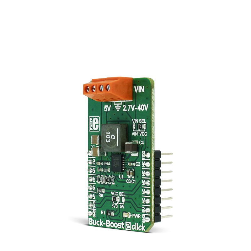
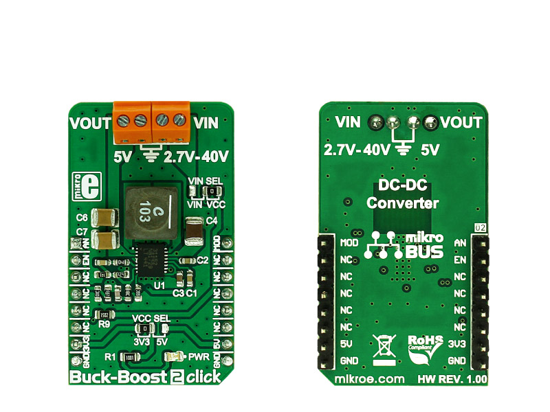
Buck-Boost 2 click is an advanced DC-DC step-down/step-up regulator (buck/boost), which is able to provide regulated 5V on its output, regardless of the input voltage. The input voltage can range from 2.7V up to 40V.

No Abuse Reported

Do you want to subscribe in order to receive notifications regarding "Buck-Boost 2 click" changes.

Do you want to unsubscribe in order to stop receiving notifications regarding "Buck-Boost 2 click" changes.

Do you want to report abuse regarding "Buck-Boost 2 click".

  • mikroSDK Library 2.0.0.0
  • Comments (0)
DOWNLOAD LINK RELATED COMPILER CONTAINS
mikroBasic PRO for ARM
  • lib
  • src
  • exa
  • hlp
  • hex
  • sch
  • pcb
  • doc
mikroBasic PRO for AVR
  • lib
  • src
  • exa
  • hlp
  • hex
  • sch
  • pcb
  • doc
mikroBasic PRO for dsPIC30/33 & PIC24
  • lib
  • src
  • exa
  • hlp
  • hex
  • sch
  • pcb
  • doc
mikroBasic PRO for FT90x
  • lib
  • src
  • exa
  • hlp
  • hex
  • sch
  • pcb
  • doc
mikroBasic PRO for PIC
  • lib
  • src
  • exa
  • hlp
  • hex
  • sch
  • pcb
  • doc
mikroBasic PRO for PIC32
  • lib
  • src
  • exa
  • hlp
  • hex
  • sch
  • pcb
  • doc
mikroC PRO for ARM
  • lib
  • src
  • exa
  • hlp
  • hex
  • sch
  • pcb
  • doc
mikroC PRO for AVR
  • lib
  • src
  • exa
  • hlp
  • hex
  • sch
  • pcb
  • doc
mikroC PRO for dsPIC30/33 & PIC24
  • lib
  • src
  • exa
  • hlp
  • hex
  • sch
  • pcb
  • doc
mikroC PRO for FT90x
  • lib
  • src
  • exa
  • hlp
  • hex
  • sch
  • pcb
  • doc
mikroC PRO for PIC
  • lib
  • src
  • exa
  • hlp
  • hex
  • sch
  • pcb
  • doc
mikroC PRO for PIC32
  • lib
  • src
  • exa
  • hlp
  • hex
  • sch
  • pcb
  • doc
mikroPascal PRO for ARM
  • lib
  • src
  • exa
  • hlp
  • hex
  • sch
  • pcb
  • doc
mikroPascal PRO for AVR
  • lib
  • src
  • exa
  • hlp
  • hex
  • sch
  • pcb
  • doc
mikroPascal PRO for dsPIC30/33 & PIC24
  • lib
  • src
  • exa
  • hlp
  • hex
  • sch
  • pcb
  • doc
mikroPascal PRO for FT90x
  • lib
  • src
  • exa
  • hlp
  • hex
  • sch
  • pcb
  • doc
mikroPascal PRO for PIC
  • lib
  • src
  • exa
  • hlp
  • hex
  • sch
  • pcb
  • doc
mikroPascal PRO for PIC32
  • lib
  • src
  • exa
  • hlp
  • hex
  • sch
  • pcb
  • doc

mikroSDK Library Blog

Buck-Boost 2 click

Buck-Boost 2 click

Native view of the Buck-Boost 2 click board.

View full image
Buck-Boost 2 click

Buck-Boost 2 click

Front and back view of the Buck-Boost 2 click board.

View full image

Library Description

The library carries functions necessary to have complete control over all functionalities of the Click board.

Key functions:

  • void buckboost2_powerON() - Turns on the device.
  • void buckboost2_powerOFF() - Turns off the device.
  • void buckboost2_setMode(uint8_t mode) - Sets the working mode.

Examples Description

The demo application is composed of three sections:

  • System Initialization - Initialization of the PWM and RST pin as OUTPUT.
  • Application Initialization (code snippet) - Initializes the Driver init and turns ON the chip and settings mode with improvement current.
  • Application Task - The lick has a constant output voltage of 5V, no additional settings are required.
void applicationInit()
{
 buckboost2_gpioDriverInit( (T_BUCKBOOST2_P)&_MIKROBUS1_GPIO );
 buckboost2_powerON();
 buckboost2_setMode(_BUCKBOOST2_WITH_IMPROVEMENT);
}

Additional notes and information

Depending on the development board you are using, you may need USB UART click,  USB UART 2 click or RS232 click to connect to your PC, for development systems with no UART to USB interface available on the board. The terminal available in all MikroElektronika compilers, or any other terminal application of your choice, can be used to read the message.

ALSO FROM THIS AUTHOR

Current 5 Click

0

Current 5 Click is a compact add-on board that provides a precise and accurate current sensing solution. This board features the INA381, a high-speed current-sense amplifier with an integrated comparator from Texas Instruments. This device has selectable operating modes (transparent or latched) and detects overcurrent conditions by measuring the voltage developed across a current shunt resistor. Then it compares that voltage to a user-defined threshold limit set by the comparator reference potentiometer. The current-shunt monitor can measure differential voltage signals on common-mode voltages that vary from –0.2V to 26V, independent of the supply voltage. This Click board™ delivers higher performance to applications such as test and measurement, load and power supplies monitoring, low-side phase motor control, and many more.

[Learn More]

DC Motor click

5

This is a simple demonstration of using the DRV8833 dual bridge motor driver (http://www.ti.com/product/drv8833), which is being used for controlling DC brush motors, a bipolar stepper motor, solenoids, or other inductive loads.

[Learn More]

ADC 6 Click

0

ADC 6 Click is an advanced 24bit multichannel analog to digital converter (ADC), with 8 fully differential or 15 single ended/pseudo differential sampling inputs, and very flexible routing capabilities. The Click board has two 2x10 pin headers, used both to configure the device and connect the input channels.

[Learn More]