TOP Contributors

  1. MIKROE (2662 codes)
  2. Alcides Ramos (357 codes)
  3. Shawon Shahryiar (307 codes)
  4. jm_palomino (112 codes)
  5. Chisanga Mumba (90 codes)
  6. S P (73 codes)
  7. dany (71 codes)
  8. MikroBUS.NET Team (35 codes)
  9. NART SCHINACKOW (34 codes)
  10. Armstrong Subero (27 codes)

Most Downloaded

  1. Timer Calculator (137026 times)
  2. FAT32 Library (70151 times)
  3. Network Ethernet Library (56032 times)
  4. USB Device Library (46355 times)
  5. Network WiFi Library (41970 times)
  6. FT800 Library (41297 times)
  7. GSM click (29068 times)
  8. mikroSDK (26503 times)
  9. PID Library (26452 times)
  10. microSD click (25432 times)
Libstock prefers package manager

Package Manager

We strongly encourage users to use Package manager for sharing their code on Libstock website, because it boosts your efficiency and leaves the end user with no room for error. [more info]

< Back
mikroSDK Library

6DOF IMU 10 click

Rating:

5

Author: MIKROE

Last Updated: 2020-01-29

Package Version: 1.0.0.0

mikroSDK Library: 1.0.0.0

Category: Motion

Downloaded: 2353 times

Not followed.

License: MIT license  

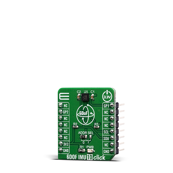
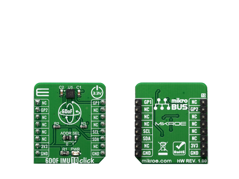
6DOF IMU 10 Click is a Click board which features the KMX62-1031, a 6 Degrees-of-Freedom inertial sensor system that features 16-bit digital outputs accessed through I2C communication from Kionix.

No Abuse Reported

Do you want to subscribe in order to receive notifications regarding "6DOF IMU 10 click" changes.

Do you want to unsubscribe in order to stop receiving notifications regarding "6DOF IMU 10 click" changes.

Do you want to report abuse regarding "6DOF IMU 10 click".

  • mikroSDK Library 2.0.0.0
  • Comments (0)
DOWNLOAD LINK RELATED COMPILER CONTAINS
mikroBasic PRO for ARM
  • lib
  • src
  • exa
  • hlp
  • hex
  • sch
  • pcb
  • doc
mikroBasic PRO for AVR
  • lib
  • src
  • exa
  • hlp
  • hex
  • sch
  • pcb
  • doc
mikroBasic PRO for dsPIC30/33 & PIC24
  • lib
  • src
  • exa
  • hlp
  • hex
  • sch
  • pcb
  • doc
mikroBasic PRO for FT90x
  • lib
  • src
  • exa
  • hlp
  • hex
  • sch
  • pcb
  • doc
mikroBasic PRO for PIC
  • lib
  • src
  • exa
  • hlp
  • hex
  • sch
  • pcb
  • doc
mikroBasic PRO for PIC32
  • lib
  • src
  • exa
  • hlp
  • hex
  • sch
  • pcb
  • doc
mikroC PRO for ARM
  • lib
  • src
  • exa
  • hlp
  • hex
  • sch
  • pcb
  • doc
mikroC PRO for AVR
  • lib
  • src
  • exa
  • hlp
  • hex
  • sch
  • pcb
  • doc
mikroC PRO for dsPIC30/33 & PIC24
  • lib
  • src
  • exa
  • hlp
  • hex
  • sch
  • pcb
  • doc
mikroC PRO for FT90x
  • lib
  • src
  • exa
  • hlp
  • hex
  • sch
  • pcb
  • doc
mikroC PRO for PIC
  • lib
  • src
  • exa
  • hlp
  • hex
  • sch
  • pcb
  • doc
mikroC PRO for PIC32
  • lib
  • src
  • exa
  • hlp
  • hex
  • sch
  • pcb
  • doc
mikroPascal PRO for ARM
  • lib
  • src
  • exa
  • hlp
  • hex
  • sch
  • pcb
  • doc
mikroPascal PRO for AVR
  • lib
  • src
  • exa
  • hlp
  • hex
  • sch
  • pcb
  • doc
mikroPascal PRO for dsPIC30/33 & PIC24
  • lib
  • src
  • exa
  • hlp
  • hex
  • sch
  • pcb
  • doc
mikroPascal PRO for FT90x
  • lib
  • src
  • exa
  • hlp
  • hex
  • sch
  • pcb
  • doc
mikroPascal PRO for PIC
  • lib
  • src
  • exa
  • hlp
  • hex
  • sch
  • pcb
  • doc
mikroPascal PRO for PIC32
  • lib
  • src
  • exa
  • hlp
  • hex
  • sch
  • pcb
  • doc

mikroSDK Library Blog

6DOF IMU 10 click

6DOF IMU 10 click

Native view of the 6DOF IMU 10 click board.

View full image
6DOF IMU 10 click

6DOF IMU 10 click

Front and back view of the 6DOF IMU 10 click board.

View full image

Library Description

The library performs a magnetometer, accelerometer and temperature measurements and control of the 6DOF IMU 10 Click board. User also can select a desired range, scale and other config for the desired measurement. For more details check documentation.

Key functions:

  • void c6dofimu10_default_cfg ( void ) - Default module configuration function
  • void c6dofimu10_get_accel_axis ( c6dofimu10_axis_t *axis ) - Accelerometer axis data
  • void c6dofimu10_get_mag_axis ( c6dofimu10_axis_t *axis ) - Magnetometer axis data

Examples description

The application is composed of three sections :

  • System Initialization - Initializes I2C driver and GP1 - GP2 pins used as interrupt pins. And initializes the LOG module.
  • Application Initialization - Runs a communication test that reads device id (registry Who_I_AM). It then starts the default module config that sets the module to its initial state of operation.
  • Application Task - Reads the accelerometer and magnetometer axis data. And reads temperature values. All data logs on the USBUART.
void application_task ( )
{
    c6dofimu10_axis_t accel_axis;
    c6dofimu10_axis_t mag_axis;
    float temperature;

    c6dofimu10_get_accel_axis ( &accel_axis );
    c6dofimu10_get_mag_axis ( &mag_axis );
    temperature = c6dofimu10_get_temperature ( C6DOFIMU10_TEMP_FORMAT_CELSIUS );

    mikrobus_logWrite( "-- Accelerometer axis --", _LOG_LINE );
    app_display_axis_data( &accel_axis );
    Delay_ms( 2000 );

    mikrobus_logWrite( "-- Magnetometer axis --", _LOG_LINE );
    app_display_axis_data( &mag_axis );
    Delay_ms( 2000 );

    mikrobus_logWrite( "-- Temperature data --", _LOG_LINE );
    app_display_temp_data( temperature );
    Delay_ms( 2000 );
}


Additional Functions :

  • app_display_axis_data ( ) - Display (accel and mag) axis data
  • app_display_temp_data ( ) - Display temperature data

Other mikroE Libraries used in the example:

  • I2C Library
  • UART Library
  • Conversions Library

Additional notes and informations

Depending on the development board you are using, you may need USB UART clickUSB UART 2 click or RS232 click to connect to your PC, for development systems with no UART to USB interface available on the board. The terminal available in all MikroElektronika compilers, or any other terminal application of your choice, can be used to read the message.

ALSO FROM THIS AUTHOR

Opto 3 click

0

Opto 3 click is a relay Click board™, equipped with two pairs of optically isolated solid-state relays (SSR).

[Learn More]

Color 2 click

1

Color 2 click carries the ISL29125 RGB color light sensor. It detects red, green and blue in a variety of lighting conditions, outputting 16-bit resolution data in a 5.7m lux-10,000 lux measuring range. The board communicates with the target MCU through the mikroBUSâ„¢ I2C interface (SCL and SDA pins).

[Learn More]

Angle 10 click

0

Angle 10 Click is a compact add-on board that detects the absolute angular position of a permanent magnet. This board features the AS5070A, a high-resolution angular position sensor with an analog output for precise absolute angle measurement from ams AG. Based on a Hall sensor technology, the AS5070A measures the orthogonal component of the flux density over a full-turn rotation and compensates for external stray magnetic fields with a robust architecture based on a 14-bit sensor array and analog front-end. Only a simple two-pole magnet rotating over the center of the AS5070A is required to measure the angle, providing an instant indication of the magnet’s angular position.

[Learn More]