TOP Contributors

  1. MIKROE (2784 codes)
  2. Alcides Ramos (405 codes)
  3. Shawon Shahryiar (307 codes)
  4. jm_palomino (133 codes)
  5. Bugz Bensce (97 codes)
  6. S P (73 codes)
  7. dany (71 codes)
  8. MikroBUS.NET Team (35 codes)
  9. NART SCHINACKOW (34 codes)
  10. Armstrong Subero (27 codes)

Most Downloaded

  1. Timer Calculator (141930 times)
  2. FAT32 Library (75080 times)
  3. Network Ethernet Library (59378 times)
  4. USB Device Library (49369 times)
  5. Network WiFi Library (45192 times)
  6. FT800 Library (44749 times)
  7. GSM click (31327 times)
  8. mikroSDK (30284 times)
  9. microSD click (27692 times)
  10. PID Library (27583 times)
Libstock prefers package manager

Package Manager

We strongly encourage users to use Package manager for sharing their code on Libstock website, because it boosts your efficiency and leaves the end user with no room for error. [more info]

< Back
mikroSDK Library

VCP Monitor click

Rating:

5

Author: MIKROE

Last Updated: 2020-03-16

Package Version: 1.0.0.0

mikroSDK Library: 1.0.0.0

Category: Current sensor

Downloaded: 3483 times

Not followed.

License: MIT license  

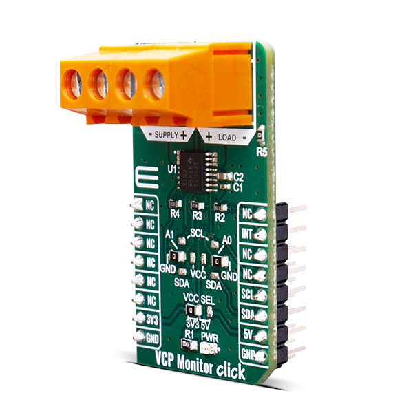
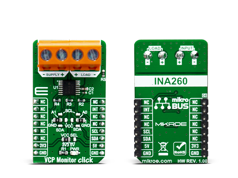
The VCP Monitor Click is add-on board power monitor system. This Click board is based on INA260AIPWR - precision digital current and power monitor with low-drift, integrated precision shunt resistor, from Texas Instruments.

No Abuse Reported

Do you want to subscribe in order to receive notifications regarding "VCP Monitor click" changes.

Do you want to unsubscribe in order to stop receiving notifications regarding "VCP Monitor click" changes.

Do you want to report abuse regarding "VCP Monitor click".

  • mikroSDK Library 2.0.0.0
  • Comments (0)
DOWNLOAD LINK RELATED COMPILER CONTAINS
mikroBasic PRO for ARM
  • lib
  • src
  • exa
  • hlp
  • hex
  • sch
  • pcb
  • doc
mikroBasic PRO for AVR
  • lib
  • src
  • exa
  • hlp
  • hex
  • sch
  • pcb
  • doc
mikroBasic PRO for dsPIC30/33 & PIC24
  • lib
  • src
  • exa
  • hlp
  • hex
  • sch
  • pcb
  • doc
mikroBasic PRO for FT90x
  • lib
  • src
  • exa
  • hlp
  • hex
  • sch
  • pcb
  • doc
mikroBasic PRO for PIC
  • lib
  • src
  • exa
  • hlp
  • hex
  • sch
  • pcb
  • doc
mikroBasic PRO for PIC32
  • lib
  • src
  • exa
  • hlp
  • hex
  • sch
  • pcb
  • doc
mikroC PRO for ARM
  • lib
  • src
  • exa
  • hlp
  • hex
  • sch
  • pcb
  • doc
mikroC PRO for AVR
  • lib
  • src
  • exa
  • hlp
  • hex
  • sch
  • pcb
  • doc
mikroC PRO for dsPIC30/33 & PIC24
  • lib
  • src
  • exa
  • hlp
  • hex
  • sch
  • pcb
  • doc
mikroC PRO for FT90x
  • lib
  • src
  • exa
  • hlp
  • hex
  • sch
  • pcb
  • doc
mikroC PRO for PIC
  • lib
  • src
  • exa
  • hlp
  • hex
  • sch
  • pcb
  • doc
mikroC PRO for PIC32
  • lib
  • src
  • exa
  • hlp
  • hex
  • sch
  • pcb
  • doc
mikroPascal PRO for ARM
  • lib
  • src
  • exa
  • hlp
  • hex
  • sch
  • pcb
  • doc
mikroPascal PRO for AVR
  • lib
  • src
  • exa
  • hlp
  • hex
  • sch
  • pcb
  • doc
mikroPascal PRO for dsPIC30/33 & PIC24
  • lib
  • src
  • exa
  • hlp
  • hex
  • sch
  • pcb
  • doc
mikroPascal PRO for FT90x
  • lib
  • src
  • exa
  • hlp
  • hex
  • sch
  • pcb
  • doc
mikroPascal PRO for PIC
  • lib
  • src
  • exa
  • hlp
  • hex
  • sch
  • pcb
  • doc
mikroPascal PRO for PIC32
  • lib
  • src
  • exa
  • hlp
  • hex
  • sch
  • pcb
  • doc

mikroSDK Library Blog

VCP Monitor Click

VCP Monitor Click

Native view of the VCP Monitor Click board.

View full image
VCP Monitor Click

VCP Monitor Click

Front and back view of the VCP Monitor Click board.

View full image

Library Description

The library contains basic communication with the module and allows the user to read and write data to the module. The user can read the current data of current, voltage and power measured by the sensor.

Key functions:

  • float vcpmonitor_get_voltage ( void ) - Reads voltage data in mV
  • float vcpmonitor_get_current ( void ) - Reads current data in mA
  • float vcpmonitor_get_power ( void ) - Reads power data in mW

Examples description

The application is composed of three sections :

  • System Initialization - Initializes I2C module and INT pin on INPUT
  • Application Initialization - Initializes driver init, check device ID and manufacture ID, start default configuration.
  • Application Task - Reads Current, Voltage and Power data. This data logs to USB UART every 1500ms.
void application_task ( )
{
    float current_data;
    float voltage_data;
    float power_data;
    
    current_data = vcpmonitor_get_current(  );
    IntToStr( current_data, demo_text );
    mikrobus_logWrite( ">> Current data: ", _LOG_TEXT );
    mikrobus_logWrite( demo_text, _LOG_TEXT );
    mikrobus_logWrite( " mA", _LOG_LINE );
     
    voltage_data = vcpmonitor_get_voltage(  );
    IntToStr( voltage_data, demo_text );
    mikrobus_logWrite( ">> Voltage data: ", _LOG_TEXT );
    mikrobus_logWrite( demo_text, _LOG_TEXT );
    mikrobus_logWrite( " mV", _LOG_LINE );
    
    power_data = vcpmonitor_get_power(  );
    IntToStr( power_data, demo_text );
    mikrobus_logWrite( ">> Power data: ", _LOG_TEXT );
    mikrobus_logWrite( demo_text, _LOG_TEXT );
    mikrobus_logWrite( " mW", _LOG_LINE );
    
    mikrobus_logWrite( " ------------------------------- ", _LOG_LINE );
    Delay_ms( 1500 );
}

Other mikroE Libraries used in the example:

  • I2C Library
  • Conversions library

Additional notes and informations

Depending on the development board you are using, you may need USB UART clickUSB UART 2 click or RS232 click to connect to your PC, for development systems with no UART to USB interface available on the board. The terminal available in all MikroElektronika compilers, or any other terminal application of your choice, can be used to read the message.

ALSO FROM THIS AUTHOR

Hall Current 17 Click

0

Hall Current 17 Click is a compact add-on board that contains a precise solution for AC/DC current sensing. This board features the ACS37010, a high-accuracy current sensor from Allegro MicroSystems. The ACS37010 has a high operating bandwidth of 450kHz and a fast response time of 1.3μs response time. It features a highly isolated compact surface-mount package, low internal primary conductor resistance, low sensitivity error, low offset voltage over temperature, and more.

[Learn More]

2x5W Amp click

6

2x5W AMP click functions as an amplifier and features the TDA7491LP 2x5-watt dual BTL class-D audio amplifier. The click is designed to run on either 3.3V or 5V power supply. It communicates with the target MCU over the following pins on the mikroBUSâ„¢ line: AN, RST, CS, PWM, INT.

[Learn More]

MCP2518FD click

5

MCP2518FD Click is a compact add-on board representing a complete CAN solution used as a control node in a CAN network. This board features the MCP2518FD, an external CAN FD controller with an SPI interface, and a high-speed CAN transceiver, the ATA6563, both from Microchip. The ATA6563, a low-level physical layer IC (PHY), provides a physical connection with the CAN bus itself, while the CAN controller MCP2518FD represents an interface between the MCU and the PHY. It features three operating modes with dedicated fail-safe features, remote wake-up via CAN, and ideally passive behavior when powered off on the CAN bus. This Click boardâ„¢ is suitable for developing a wide range of automotive diagnostic applications, even on MCUs that do not natively support CAN interface.

[Learn More]