TOP Contributors

  1. MIKROE (2784 codes)
  2. Alcides Ramos (405 codes)
  3. Shawon Shahryiar (307 codes)
  4. jm_palomino (133 codes)
  5. Bugz Bensce (97 codes)
  6. S P (73 codes)
  7. dany (71 codes)
  8. MikroBUS.NET Team (35 codes)
  9. NART SCHINACKOW (34 codes)
  10. Armstrong Subero (27 codes)

Most Downloaded

  1. Timer Calculator (141679 times)
  2. FAT32 Library (74727 times)
  3. Network Ethernet Library (59203 times)
  4. USB Device Library (49213 times)
  5. Network WiFi Library (44988 times)
  6. FT800 Library (44517 times)
  7. GSM click (31195 times)
  8. mikroSDK (30081 times)
  9. microSD click (27577 times)
  10. PID Library (27537 times)
Libstock prefers package manager

Package Manager

We strongly encourage users to use Package manager for sharing their code on Libstock website, because it boosts your efficiency and leaves the end user with no room for error. [more info]

< Back
mikroSDK Library

EXPAND 5 click

Rating:

5

Author: MIKROE

Last Updated: 2020-07-21

Package Version: 1.0.0.0

mikroSDK Library: 1.0.0.0

Category: Port expander

Downloaded: 3009 times

Not followed.

License: MIT license  

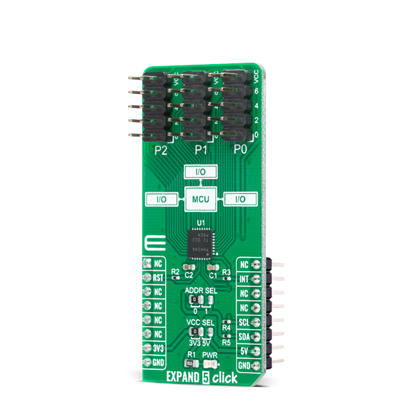
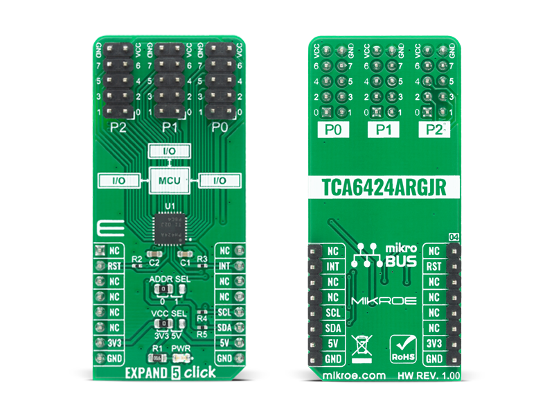
EXPAND 5 Click features a low-voltage 24-bit I2C and SMBus I/O expander. This 24-bit I/O expander is designed to provide general-purpose remote I/O expansion for most microcontroller families via the I2C serial interface.

No Abuse Reported

Do you want to subscribe in order to receive notifications regarding "EXPAND 5 click" changes.

Do you want to unsubscribe in order to stop receiving notifications regarding "EXPAND 5 click" changes.

Do you want to report abuse regarding "EXPAND 5 click".

  • mikroSDK Library 2.0.0.0
  • Comments (0)
DOWNLOAD LINK RELATED COMPILER CONTAINS
mikroBasic PRO for ARM
  • lib
  • src
  • exa
  • hlp
  • hex
  • sch
  • pcb
  • doc
mikroBasic PRO for AVR
  • lib
  • src
  • exa
  • hlp
  • hex
  • sch
  • pcb
  • doc
mikroBasic PRO for dsPIC30/33 & PIC24
  • lib
  • src
  • exa
  • hlp
  • hex
  • sch
  • pcb
  • doc
mikroBasic PRO for FT90x
  • lib
  • src
  • exa
  • hlp
  • hex
  • sch
  • pcb
  • doc
mikroBasic PRO for PIC
  • lib
  • src
  • exa
  • hlp
  • hex
  • sch
  • pcb
  • doc
mikroBasic PRO for PIC32
  • lib
  • src
  • exa
  • hlp
  • hex
  • sch
  • pcb
  • doc
mikroC PRO for ARM
  • lib
  • src
  • exa
  • hlp
  • hex
  • sch
  • pcb
  • doc
mikroC PRO for AVR
  • lib
  • src
  • exa
  • hlp
  • hex
  • sch
  • pcb
  • doc
mikroC PRO for dsPIC30/33 & PIC24
  • lib
  • src
  • exa
  • hlp
  • hex
  • sch
  • pcb
  • doc
mikroC PRO for FT90x
  • lib
  • src
  • exa
  • hlp
  • hex
  • sch
  • pcb
  • doc
mikroC PRO for PIC
  • lib
  • src
  • exa
  • hlp
  • hex
  • sch
  • pcb
  • doc
mikroC PRO for PIC32
  • lib
  • src
  • exa
  • hlp
  • hex
  • sch
  • pcb
  • doc
mikroPascal PRO for ARM
  • lib
  • src
  • exa
  • hlp
  • hex
  • sch
  • pcb
  • doc
mikroPascal PRO for AVR
  • lib
  • src
  • exa
  • hlp
  • hex
  • sch
  • pcb
  • doc
mikroPascal PRO for dsPIC30/33 & PIC24
  • lib
  • src
  • exa
  • hlp
  • hex
  • sch
  • pcb
  • doc
mikroPascal PRO for FT90x
  • lib
  • src
  • exa
  • hlp
  • hex
  • sch
  • pcb
  • doc
mikroPascal PRO for PIC
  • lib
  • src
  • exa
  • hlp
  • hex
  • sch
  • pcb
  • doc
mikroPascal PRO for PIC32
  • lib
  • src
  • exa
  • hlp
  • hex
  • sch
  • pcb
  • doc

mikroSDK Library Blog

EXPAND 5 Click

EXPAND 5 Click

Native view of the EXPAND 5 Click board.

View full image
EXPAND 5 Click

EXPAND 5 Click

Front and back view of the EXPAND 5 Click board.

View full image

Library Description

The library covers necessary functions that enables the usage of the EXPAND 5 click board. User can configure polarity and direction of every pin and get or set state of each and every pin.

Key functions:

  • void expand5_set_all_dir( uint8_t bank0, uint8_t bank1, uint8_t bank2 ); - Function is used to set pins' direction ( I/O ) setting in all banks.
  • void expand5_write_pin ( uint16_t pin, uint8_t pin_val ); - Function is used to set a single output pin's logic level.
  • void expand5_write_all_banks ( uint8_t bank0, uint8_t bank1, uint8_t bank2 ); - Function is used to set logic levels in all banks.

Examples description

The application is composed of three sections :

  • System Initialization - Initializes I2C module, LOG structure and sets RST pin as output and INT pin as input.
  • Application Initialization - Initalizes I2C driver, resets the device, configures all pins as output and makes an initial log.
  • Application Task - (code snippet) This example shows the capabilities of the EXPAND 5 click by toggling each of 24 available pins.
void application_task ( )
{
    for ( pin_num = EXPAND5_P00; pin_num <= EXPAND5_P27; pin_num++ )
    {
        expand5_write_all_banks ( bank_low, bank_low, bank_low );
        expand5_write_pin ( pin_num, EXPAND5_HIGH );
        mikrobus_logWrite( "Pin ", _LOG_TEXT );
        ByteToStr( pin_num, log_txt );
        Ltrim( log_txt );
        mikrobus_logWrite( log_txt, _LOG_TEXT );
        mikrobus_logWrite( " is high!", _LOG_LINE );

        Delay_ms( 100 );
        expand5_write_all_banks ( bank_low, bank_low, bank_low );
    }
    mikrobus_logWrite( "-------------------", _LOG_LINE );
    Delay_ms( 1000 );
}

Other mikroE Libraries used in the example:

  • I2C
  • UART
  • Conversions

Additional notes and informations

Depending on the development board you are using, you may need USB UART clickUSB UART 2 click or RS232 click to connect to your PC, for development systems with no UART to USB interface available on the board. The terminal available in all MikroElektronika compilers, or any other terminal application of your choice, can be used to read the message.

ALSO FROM THIS AUTHOR

BarGraph click

0

This is a demonstration example for BarGraph click. Bar Graph is representing ADC value measured on Poetntiometer P1. On Potentiometer P2 user can adjust PWM for LCD backlight.

[Learn More]

IR Grid Click

0

IR Grid Click is a thermal imaging sensor. It has an array of 64 very sensitive factory calibrated IR elements (pixels), arranged in 4 rows of 16 pixels, each measuring an object temperature up to 300˚C within its local Field of View (FOV). The MLX90621ESF-BAD IR sensor used on this Click board™ has only four pins, and it is mounted inside of the industry standard TO39 package. It is equipped with 2Kbit of EEPROM for storing the compensation and calibration parameters.

[Learn More]

Button G Click

0

Button G Click is the simplest solution for adding a single pushbutton to your design. The button itself is transparent, 6.8mm in diameter and has a green LED backlight. When pressed, it sends an interrupt signal to the target board microcontroller. The backlight LED is controlled separately through the mikroBUS PWM pin, so you can program all kinds of patterns (varying level of light intensity or rate of blinking on subsequent button presses). The board can use either a 3.3V or a 5V power supply.

[Learn More]