TOP Contributors

  1. MIKROE (2784 codes)
  2. Alcides Ramos (403 codes)
  3. Shawon Shahryiar (307 codes)
  4. jm_palomino (132 codes)
  5. Bugz Bensce (97 codes)
  6. S P (73 codes)
  7. dany (71 codes)
  8. MikroBUS.NET Team (35 codes)
  9. NART SCHINACKOW (34 codes)
  10. Armstrong Subero (27 codes)

Most Downloaded

  1. Timer Calculator (140939 times)
  2. FAT32 Library (73501 times)
  3. Network Ethernet Library (58318 times)
  4. USB Device Library (48484 times)
  5. Network WiFi Library (44090 times)
  6. FT800 Library (43662 times)
  7. GSM click (30545 times)
  8. mikroSDK (29266 times)
  9. PID Library (27205 times)
  10. microSD click (26929 times)
Libstock prefers package manager

Package Manager

We strongly encourage users to use Package manager for sharing their code on Libstock website, because it boosts your efficiency and leaves the end user with no room for error. [more info]

< Back
mikroSDK Library

UWB click

Rating:

5

Author: MIKROE

Last Updated: 2020-08-06

Package Version: 1.0.0.0

mikroSDK Library: 1.0.0.0

Category: Wireless connectivity

Downloaded: 3205 times

Not followed.

License: MIT license  

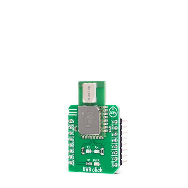
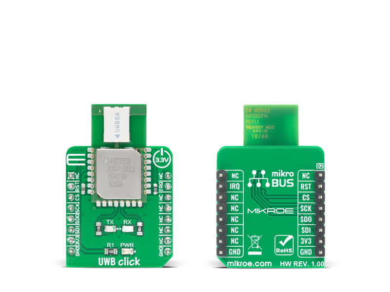
UWB Click is an Ultra-Wideband transceiver Click board that can be used in 2-way ranging or TDOA location systems to locate assets to a precision of 10 cm and supports data rates of up to 6.8 Mbps. This board features the DWM1000 module based on Decawave's DW1000 Ultra-Wideband (UWB) transceiver from Decawave Limited.

No Abuse Reported

Do you want to subscribe in order to receive notifications regarding "UWB click" changes.

Do you want to unsubscribe in order to stop receiving notifications regarding "UWB click" changes.

Do you want to report abuse regarding "UWB click".

  • mikroSDK Library 2.0.0.0
  • Comments (0)
DOWNLOAD LINK RELATED COMPILER CONTAINS
mikroBasic PRO for ARM
  • lib
  • src
  • exa
  • hlp
  • hex
  • sch
  • pcb
  • doc
mikroBasic PRO for AVR
  • lib
  • src
  • exa
  • hlp
  • hex
  • sch
  • pcb
  • doc
mikroBasic PRO for dsPIC30/33 & PIC24
  • lib
  • src
  • exa
  • hlp
  • hex
  • sch
  • pcb
  • doc
mikroBasic PRO for FT90x
  • lib
  • src
  • exa
  • hlp
  • hex
  • sch
  • pcb
  • doc
mikroBasic PRO for PIC
  • lib
  • src
  • exa
  • hlp
  • hex
  • sch
  • pcb
  • doc
mikroBasic PRO for PIC32
  • lib
  • src
  • exa
  • hlp
  • hex
  • sch
  • pcb
  • doc
mikroC PRO for ARM
  • lib
  • src
  • exa
  • hlp
  • hex
  • sch
  • pcb
  • doc
mikroC PRO for AVR
  • lib
  • src
  • exa
  • hlp
  • hex
  • sch
  • pcb
  • doc
mikroC PRO for dsPIC30/33 & PIC24
  • lib
  • src
  • exa
  • hlp
  • hex
  • sch
  • pcb
  • doc
mikroC PRO for FT90x
  • lib
  • src
  • exa
  • hlp
  • hex
  • sch
  • pcb
  • doc
mikroC PRO for PIC
  • lib
  • src
  • exa
  • hlp
  • hex
  • sch
  • pcb
  • doc
mikroC PRO for PIC32
  • lib
  • src
  • exa
  • hlp
  • hex
  • sch
  • pcb
  • doc
mikroPascal PRO for ARM
  • lib
  • src
  • exa
  • hlp
  • hex
  • sch
  • pcb
  • doc
mikroPascal PRO for AVR
  • lib
  • src
  • exa
  • hlp
  • hex
  • sch
  • pcb
  • doc
mikroPascal PRO for dsPIC30/33 & PIC24
  • lib
  • src
  • exa
  • hlp
  • hex
  • sch
  • pcb
  • doc
mikroPascal PRO for FT90x
  • lib
  • src
  • exa
  • hlp
  • hex
  • sch
  • pcb
  • doc
mikroPascal PRO for PIC
  • lib
  • src
  • exa
  • hlp
  • hex
  • sch
  • pcb
  • doc
mikroPascal PRO for PIC32
  • lib
  • src
  • exa
  • hlp
  • hex
  • sch
  • pcb
  • doc

mikroSDK Library Blog

UWB Click

UWB Click

Native view of the UWB Click board.

View full image
UWB Click

UWB Click

Front and back view of the UWB Click board.

View full image

Library Description

Library provides complete control of device. You have communication functions for controlling device, writing, reading functions, controlling pins state. There are functions for configurating every aspect of communication, after you set every mode, channel, frequency... With function uwb_tune_config library will set some additional setting relative to previous set configuration. You can set and check communication stage with eather interrupt mask or status register. For communication you have few function like uwb_get_transmit( gets received data ), uwb_get_transmit_len( gets received data length ), uwb_set_transmit( set data to trasnimt ), and uwb_start_transceiver( starts receiving or transmiting data relative to mode set by configuration ).

Key functions:

  • void uwb_generic_write ( uint8_t reg_adr, uint16_t offset, uint8_t *tx_buf, uint16_t buf_len ) - Writing data to device
  • void uwb_generic_read ( uint8_t reg_adr, uint16_t offset, uint8_t *rx_buf, uint16_t buf_len ) - Reading data from device
  • void uwb_set_mode ( uint8_t mode ) - Setting device in one working mode
  • void uwb_get_transmit ( uint8_t *rx_buf, uint16_t len_buf ) - Get received data
  • void uwb_set_transmit ( uint8_t *tx_buf, uint16_t len_buf ) - Set data to transmit
  • void uwb_start_transceiver ( void ) - Start receiving or transmitig data

Examples description

The application is composed of three sections :

  • System Initialization - Initialization of SPI module and additional pins
  • Application Initialization - Mapping GPIO and SPI module, setting device working mode setting device ID and default configuration for selected mode.
  • Application Task - Checks if interrupt occured for previous set mode. * TX mode: Transmit data and then set delay for 2 seconds. * RX mode: Receive data and logs it.
void application_task ( )
{
    dev_status = uwb_get_qint_pin_status(  );

    if ( UWB_MODE_RX == dev_mode )
    {
        if ( dev_status )
        {
            //Reading transtimed data logs it and reseting to receive mode
            uwb_set_mode( UWB_MODE_IDLE );
            uwb_clear_status(  );
            temp_len = uwb_get_transmit_len(  );
            uwb_get_transmit( &transmit_data[ 0 ], temp_len );
            mikrobus_logWrite( "Received data:", _LOG_TEXT );
            mikrobus_logWrite( transmit_data, _LOG_LINE );
            mikrobus_logWrite( " - Receive done - ", _LOG_LINE );
            uwb_set_mode( UWB_MODE_RX );
            uwb_start_transceiver(  );
        }
    }
    else if ( UWB_MODE_TX == dev_mode )
    {
        if ( dev_status )
        {
            //Transmits data reseting to transmit mode and setts 2sec delay
            mikrobus_logWrite( " - Transmit done - ", _LOG_LINE );
            uwb_set_mode( UWB_MODE_IDLE );
            uwb_clear_status(  );
            uwb_set_transmit( &data_tx[ 0 ], 6 );
            uwb_set_mode( UWB_MODE_TX );
            uwb_start_transceiver(  );
            Delay_ms( 2000 );
        }
    }
}

Other mikroE Libraries used in the example:

  • SPI
  • UART
  • Conversions

Additional notes and informations

Depending on the development board you are using, you may need USB UART clickUSB UART 2 click or RS232 click to connect to your PC, for development systems with no UART to USB interface available on the board. The terminal available in all MikroElektronika compilers, or any other terminal application of your choice, can be used to read the message.

ALSO FROM THIS AUTHOR

Multi Stepper TB62261 Click

0

Multi Stepper Click is a compact add-on board that contains a bipolar stepper motor driver. This board features the TB62261FTG, a PHASE-in controlled bipolar stepping motor driver from Toshiba Semiconductor. It supports a PWM constant-current control drive and full-, half-, and quarter-step operation for less motor noise and smoother control. It has a wide operating voltage range of 10V to 38V with an output current capacity of 1.2A in addition to several built-in error detection circuits.

[Learn More]

ISM Click

1

ISM Click is a compact add-on board that contains a complete wireless RF digital data transceiver. This board features the RFM75, a low-power, high-performance 2.4GHz GFSK transceiver from RF Solutions. The RFM75 transceiver is configurable through SPI serial interface and operates with only 3.3V in the worldwide ISM frequency band from 2400MHz up to 2527MHz. The embedded packet processing engines enable their entire operation with a simple MCU as a radio system. Burst mode transmission and up to 2Mbps air data rate make it suitable for applications requiring ultra-low power consumption.

[Learn More]

I2C MUX 6 Click

0

I2C MUX 6 Click is a compact add-on board representing a bidirectional selector dedicated to I2C slave address conflicts applications. This board features the PCA9518, an expandable five-channel bidirectional buffer controlled by the I2C-bus from Texas Instruments. The PCA9518 overcomes the restriction of maximum bus capacitance by separating and buffering the I2C data (SDA) and clock (SCL) lines into multiple groups of 400pF I2C channels. It provides activation of the desired channel via a given Enable pin and permits extension of the I2C-bus, through an onboard expansion header, by buffering both the data (SDA) and the clock (SCL) lines enabling virtually an unlimited number of buses of 400pF.

[Learn More]