TOP Contributors

  1. MIKROE (2784 codes)
  2. Alcides Ramos (405 codes)
  3. Shawon Shahryiar (307 codes)
  4. jm_palomino (133 codes)
  5. Bugz Bensce (97 codes)
  6. S P (73 codes)
  7. dany (71 codes)
  8. MikroBUS.NET Team (35 codes)
  9. NART SCHINACKOW (34 codes)
  10. Armstrong Subero (27 codes)

Most Downloaded

  1. Timer Calculator (141514 times)
  2. FAT32 Library (74401 times)
  3. Network Ethernet Library (58914 times)
  4. USB Device Library (48964 times)
  5. Network WiFi Library (44727 times)
  6. FT800 Library (44292 times)
  7. GSM click (31003 times)
  8. mikroSDK (29859 times)
  9. PID Library (27432 times)
  10. microSD click (27410 times)
Libstock prefers package manager

Package Manager

We strongly encourage users to use Package manager for sharing their code on Libstock website, because it boosts your efficiency and leaves the end user with no room for error. [more info]

< Back
mikroSDK Library

H-Bridge 6 click

Rating:

5

Author: MIKROE

Last Updated: 2021-08-06

Package Version: 1.0.0.0

mikroSDK Library: 1.0.0.0

Category: Brushed

Downloaded: 2299 times

Not followed.

License: MIT license  

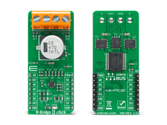
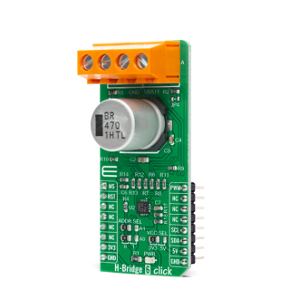
H-Bridge 6 Click is a compact add-on board that contains a DC motor driver for automotive applications. This board features the VNHD7008AY, an H-bridge motor driver for automotive DC motor driving from STMicroelectronics.

No Abuse Reported

Do you want to subscribe in order to receive notifications regarding "H-Bridge 6 click" changes.

Do you want to unsubscribe in order to stop receiving notifications regarding "H-Bridge 6 click" changes.

Do you want to report abuse regarding "H-Bridge 6 click".
  • mikroSDK Library 2.0.0.0
  • Comments (0)
DOWNLOAD LINK RELATED COMPILER CONTAINS
mikroBasic PRO for ARM
  • lib
  • src
  • exa
  • hlp
  • hex
  • sch
  • pcb
  • doc
mikroBasic PRO for AVR
  • lib
  • src
  • exa
  • hlp
  • hex
  • sch
  • pcb
  • doc
mikroBasic PRO for dsPIC30/33 & PIC24
  • lib
  • src
  • exa
  • hlp
  • hex
  • sch
  • pcb
  • doc
mikroBasic PRO for FT90x
  • lib
  • src
  • exa
  • hlp
  • hex
  • sch
  • pcb
  • doc
mikroBasic PRO for PIC
  • lib
  • src
  • exa
  • hlp
  • hex
  • sch
  • pcb
  • doc
mikroBasic PRO for PIC32
  • lib
  • src
  • exa
  • hlp
  • hex
  • sch
  • pcb
  • doc
mikroC PRO for ARM
  • lib
  • src
  • exa
  • hlp
  • hex
  • sch
  • pcb
  • doc
mikroC PRO for AVR
  • lib
  • src
  • exa
  • hlp
  • hex
  • sch
  • pcb
  • doc
mikroC PRO for dsPIC30/33 & PIC24
  • lib
  • src
  • exa
  • hlp
  • hex
  • sch
  • pcb
  • doc
mikroC PRO for FT90x
  • lib
  • src
  • exa
  • hlp
  • hex
  • sch
  • pcb
  • doc
mikroC PRO for PIC
  • lib
  • src
  • exa
  • hlp
  • hex
  • sch
  • pcb
  • doc
mikroC PRO for PIC32
  • lib
  • src
  • exa
  • hlp
  • hex
  • sch
  • pcb
  • doc
mikroPascal PRO for ARM
  • lib
  • src
  • exa
  • hlp
  • hex
  • sch
  • pcb
  • doc
mikroPascal PRO for AVR
  • lib
  • src
  • exa
  • hlp
  • hex
  • sch
  • pcb
  • doc
mikroPascal PRO for dsPIC30/33 & PIC24
  • lib
  • src
  • exa
  • hlp
  • hex
  • sch
  • pcb
  • doc
mikroPascal PRO for FT90x
  • lib
  • src
  • exa
  • hlp
  • hex
  • sch
  • pcb
  • doc
mikroPascal PRO for PIC
  • lib
  • src
  • exa
  • hlp
  • hex
  • sch
  • pcb
  • doc
mikroPascal PRO for PIC32
  • lib
  • src
  • exa
  • hlp
  • hex
  • sch
  • pcb
  • doc

mikroSDK Library Blog

H-Bridge 6 Click

H-Bridge 6 Click

Native view of the H-Bridge 6 Click board.

View full image
H-Bridge 6 Click

H-Bridge 6 Click

Front and back view of the H-Bridge 6 Click board.

View full image

Library Description

The library covers all the necessary functions to control the H-Bridge 6 Click board™. A library performs communication with the device via the I2C interface. Using the PWM function, we can adjust the engine speed and direction.

Key functions:

  • void hbridge6_generic_write ( uint8_t reg, uint8_t tx_data ) - Generic write function.
  • uint8_t hbridge6_generic_read ( uint8_t reg ) - Generic read function.
  • void hbridge6_set_direction ( uint8_t direction ) - Set the direction function.

Examples description

The application is composed of three sections :

  • System Initialization - Initializes I2C and start to write log.
  • Application Initialization - Initialization driver enables - I2C, reset the device and set default configuration, initialization and configure the PWM, also write log.
  • Application Task - (code snippet) This is an example that demonstrates the use of H-Bridge 6 Click board™. It shows moving in the clockwise direction of rotation and moving in the counterclockwise direction of rotation from slow to fast speed. All data logs write on USB uart changes.
void application_task ( )
{
    mikrobus_logWrite( "-----------------------", _LOG_LINE );
    mikrobus_logWrite( "       Clockwise       ", _LOG_LINE );
    hbridge6_set_direction( HBRIDGE6_DIRECTION_CLOCKWISE );
    pwm_duty_cycle = 100;
    
    while ( pwm_duty_cycle < ( pwm_max_duty / 3 ) )
    {
        pwm_duty_cycle += 50;
        mikrobus_logWrite( " >", _LOG_TEXT );
        hbridge6_pwm_set_duty( pwm_duty_cycle );
        Delay_ms( 100 );
    }
    
    mikrobus_logWrite( "", _LOG_LINE );
    mikrobus_logWrite( "-----------------------", _LOG_LINE );
    mikrobus_logWrite( "         Brake         ", _LOG_LINE );
    hbridge6_set_direction( HBRIDGE6_DIRECTION_BRAKE );
    Delay_ms( 3000 );

    mikrobus_logWrite( "-----------------------", _LOG_LINE );
    mikrobus_logWrite( "    Counterclockwise   ", _LOG_LINE );
    hbridge6_set_direction( HBRIDGE6_DIRECTION_COUNTERCLOCKWISE );
    pwm_duty_cycle = 100;
    Delay_ms( 1000 );

    while ( pwm_duty_cycle < ( pwm_max_duty / 3 ) )
    {
        pwm_duty_cycle += 50;
        mikrobus_logWrite( " <", _LOG_TEXT );
        hbridge6_pwm_set_duty( pwm_duty_cycle );
        Delay_ms( 100 );
    }
    
    mikrobus_logWrite( "", _LOG_LINE );
    mikrobus_logWrite( "-----------------------", _LOG_LINE );
    mikrobus_logWrite( "         Brake         ", _LOG_LINE );
    hbridge6_set_direction( HBRIDGE6_DIRECTION_BRAKE );
    Delay_ms( 1000 );
    
    hbridge6_pwm_stop( );
    Delay_ms( 2000 );
    hbridge6_pwm_start( );
    Delay_ms( 1000 );
}


  • uint32_t hbridge6_pwm_init ( uint16_t freq ) - Initializes the Timer module in PWM mode.
  • void hbridge6_pwm_set_duty ( uint16_t duty ) - The function changes PWM duty ratio.
  • void hbridge6_pwm_start( ) - Starts appropriate PWM module.
  • void hbridge6_pwm_stop( ) - Stops appropriate PWM module.

Other mikroE Libraries used in the example:

  • I2C
  • PWM
  • UART

Additional notes and informations

Depending on the development board you are using, you may need USB UART clickUSB UART 2 click or RS232 click to connect to your PC, for development systems with no UART to USB interface available on the board. The terminal available in all MikroElektronika compilers, or any other terminal application of your choice, can be used to read the message.

ALSO FROM THIS AUTHOR

RTC 4 Click

0

RTC4 Click carries DS2417, a real time clock/calendar with a 1-Wire MicroLAN interface and a programmable interrupt for system output.

[Learn More]

Pressure 19 Click

0

Pressure 19 Click is a compact add-on board that contains a board-mount pressure sensor. This board features the MLX90817, a factory-calibrated absolute pressure sensor delivering ratiometric analog output from Melexis Technologies. The MLX90817 comes with a configurable host interface that supports I2C serial communication and configurable signal processing (the user is allowed to process the output signal in analog or digital form). It measures pressure from 0.2 up to 3bar with a pressure accuracy of ±33mbar. Its DSP-based architecture using a 16bit microcontroller provides outstanding performance in terms of initial accuracy and assures operation in a temperature range of -40°C to +120°C, ensuring stable operation under extreme conditions.

[Learn More]

2x2 RGB Click

0

2x2 RGB Click is a compact add-on board that contains a matrix of 4 “intelligent” RGB elements, forming a 2x2 display screen. This board features the KTD2052A, a 12-channel RGB LED driver from Kinetic Technologies. It is a fully programmable current regulator for up to four RGB LEDs (12 LEDs in total). The LED matrix consists of four LRTB GFTG, a 6-lead in-line MULTILEDs, from ams OSRAM. The LEDs have a 120-degree viewing angle.

[Learn More]