TOP Contributors

  1. MIKROE (2784 codes)
  2. Alcides Ramos (403 codes)
  3. Shawon Shahryiar (307 codes)
  4. jm_palomino (132 codes)
  5. Bugz Bensce (97 codes)
  6. S P (73 codes)
  7. dany (71 codes)
  8. MikroBUS.NET Team (35 codes)
  9. NART SCHINACKOW (34 codes)
  10. Armstrong Subero (27 codes)

Most Downloaded

  1. Timer Calculator (140963 times)
  2. FAT32 Library (73513 times)
  3. Network Ethernet Library (58321 times)
  4. USB Device Library (48509 times)
  5. Network WiFi Library (44132 times)
  6. FT800 Library (43687 times)
  7. GSM click (30546 times)
  8. mikroSDK (29290 times)
  9. PID Library (27220 times)
  10. microSD click (26931 times)
Libstock prefers package manager

Package Manager

We strongly encourage users to use Package manager for sharing their code on Libstock website, because it boosts your efficiency and leaves the end user with no room for error. [more info]

< Back
mikroSDK Library

Boost 3 click

Rating:

5

Author: MIKROE

Last Updated: 2020-10-02

Package Version: 1.0.0.0

mikroSDK Library: 1.0.0.0

Category: Boost

Downloaded: 2733 times

Not followed.

License: MIT license  

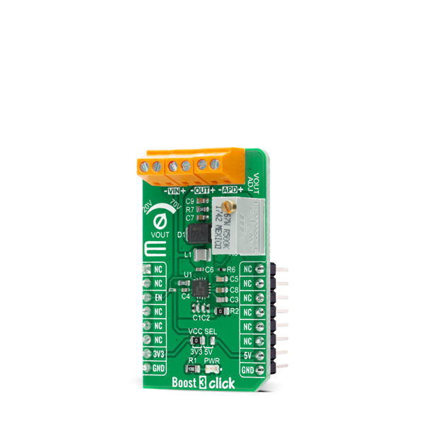
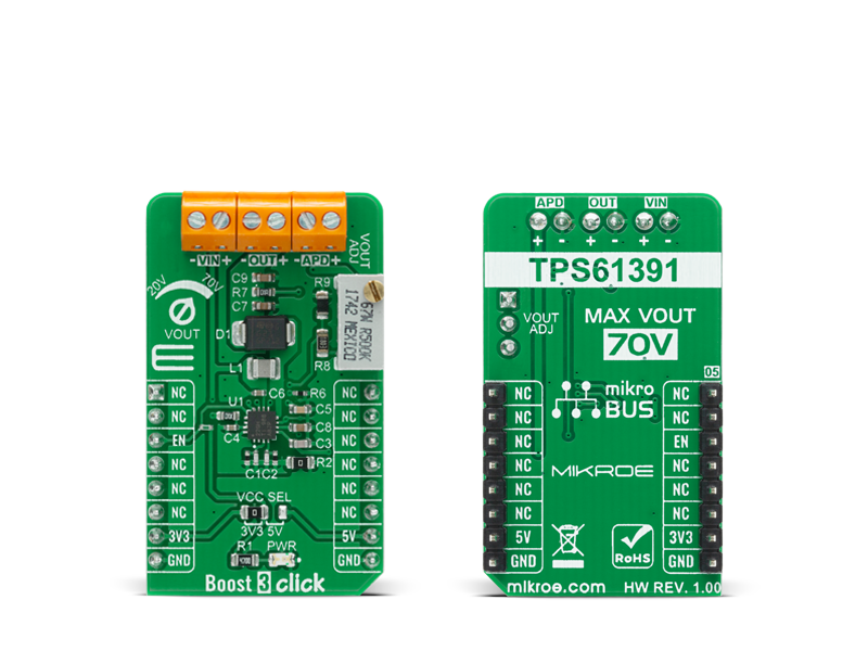
Boost 3 Click is a compact add-on board that contains a boost converter with an integrated current mirror function. This board features the TPS61391, a 700-kHz pulse-width modulating (PWM) Step-Up converter with a 70V switch FET with an input voltage up to 5.5V from Texas Instruments.

No Abuse Reported

Do you want to subscribe in order to receive notifications regarding "Boost 3 click" changes.

Do you want to unsubscribe in order to stop receiving notifications regarding "Boost 3 click" changes.

Do you want to report abuse regarding "Boost 3 click".

  • mikroSDK Library 2.0.0.0
  • Comments (0)
DOWNLOAD LINK RELATED COMPILER CONTAINS
mikroBasic PRO for ARM
  • lib
  • src
  • exa
  • hlp
  • hex
  • sch
  • pcb
  • doc
mikroBasic PRO for AVR
  • lib
  • src
  • exa
  • hlp
  • hex
  • sch
  • pcb
  • doc
mikroBasic PRO for dsPIC30/33 & PIC24
  • lib
  • src
  • exa
  • hlp
  • hex
  • sch
  • pcb
  • doc
mikroBasic PRO for FT90x
  • lib
  • src
  • exa
  • hlp
  • hex
  • sch
  • pcb
  • doc
mikroBasic PRO for PIC
  • lib
  • src
  • exa
  • hlp
  • hex
  • sch
  • pcb
  • doc
mikroBasic PRO for PIC32
  • lib
  • src
  • exa
  • hlp
  • hex
  • sch
  • pcb
  • doc
mikroC PRO for ARM
  • lib
  • src
  • exa
  • hlp
  • hex
  • sch
  • pcb
  • doc
mikroC PRO for AVR
  • lib
  • src
  • exa
  • hlp
  • hex
  • sch
  • pcb
  • doc
mikroC PRO for dsPIC30/33 & PIC24
  • lib
  • src
  • exa
  • hlp
  • hex
  • sch
  • pcb
  • doc
mikroC PRO for FT90x
  • lib
  • src
  • exa
  • hlp
  • hex
  • sch
  • pcb
  • doc
mikroC PRO for PIC
  • lib
  • src
  • exa
  • hlp
  • hex
  • sch
  • pcb
  • doc
mikroC PRO for PIC32
  • lib
  • src
  • exa
  • hlp
  • hex
  • sch
  • pcb
  • doc
mikroPascal PRO for ARM
  • lib
  • src
  • exa
  • hlp
  • hex
  • sch
  • pcb
  • doc
mikroPascal PRO for AVR
  • lib
  • src
  • exa
  • hlp
  • hex
  • sch
  • pcb
  • doc
mikroPascal PRO for dsPIC30/33 & PIC24
  • lib
  • src
  • exa
  • hlp
  • hex
  • sch
  • pcb
  • doc
mikroPascal PRO for FT90x
  • lib
  • src
  • exa
  • hlp
  • hex
  • sch
  • pcb
  • doc
mikroPascal PRO for PIC
  • lib
  • src
  • exa
  • hlp
  • hex
  • sch
  • pcb
  • doc
mikroPascal PRO for PIC32
  • lib
  • src
  • exa
  • hlp
  • hex
  • sch
  • pcb
  • doc

mikroSDK Library Blog

Boost 3 Click

Boost 3 Click

Native view of the Boost 3 Click board.

View full image
Boost 3 Click

Boost 3 Click

Front and back view of the Boost 3 Click board.

View full image

Library Description

The library covers the necessary function that enables the usage of the RTC 11 Click board. User can enable or disable the device.

Key functions:

  • void boost3_dev_enable ( uint8_t state ); - Function is used to enable or disable the device.

Examples description

The application is composed of three sections :

  • System Initialization - Initializes GPIO and LOG structures, and set CS pin as output.
  • Application Initialization - Start to write log and gives instructions to the user.
  • Application Task - Demonstrates use of Boost 3 click board by by reading user's command input from USART terminal and turning the device on or off accordingly. User can use the on-board potentiometer to adjust 'Vout' voltage.
void application_task ( )
{  
    char cmd;
    if ( UART_Rdy_Ptr() )
    {
        cmd = UART_Rd_Ptr( );
        cmd -= 48;
        boost3_dev_enable( cmd );
        if( cmd == BOOST3_ENABLE )
        {
            mikrobus_logWrite( "The device is turned on!", _LOG_LINE );
            mikrobus_logWrite( "Use on-board potentiometer", _LOG_LINE );
            mikrobus_logWrite( " to adjust 'Vout' voltage", _LOG_LINE );
        }
        else
        {
            mikrobus_logWrite( "The device is turned off!", _LOG_LINE );
        }
    }
}

Other mikroE Libraries used in the example:

  • GPIO
  • UART

Additional notes and informations

Depending on the development board you are using, you may need USB UART clickUSB UART 2 click or RS232 click to connect to your PC, for development systems with no UART to USB interface available on the board. The terminal available in all MikroElektronika compilers, or any other terminal application of your choice, can be used to read the message.

ALSO FROM THIS AUTHOR

Magneto click

1

Magneto click carries an AS5048A contactless magnetic angle position sensor. The sensing circuitry relies on the Hall Effect to detect the vector of a nearby magnetic field in a 360º two-dimensional plane parallel to the surface of the chip. AS5048A delivers precise angle measurements down to 0.05º in 14-bit resolution.

[Learn More]

DC Motor 3 Click

0

DC MOTOR 3 Click is a mikroBUS™ add-on board with a Toshiba TB6549FG full-bridge driver for direct current motors. The IC is capable of outputting currents of up to 3.5 A with 30V, making it suitable for high-power motors

[Learn More]

Stepper 9 Click

0

Stepper 9 Click is a compact add-on board that contains a bipolar stepper motor driver. This board features the TB67S581FNG, a two-phase bipolar stepping motor driver from Toshiba Semiconductor. Fabricated with the BiCD process, it supports a PWM constant-current control drive and steps resolution from full to 1/32 for less motor noise and smoother control. It has a wide operating voltage range of 8.2V to 44V with a maximum output current capacity of 2A, decay modes selection function, protection, and several anomaly detection indicators.

[Learn More]