TOP Contributors

  1. MIKROE (2784 codes)
  2. Alcides Ramos (393 codes)
  3. Shawon Shahryiar (307 codes)
  4. jm_palomino (123 codes)
  5. Bugz Bensce (97 codes)
  6. S P (73 codes)
  7. dany (71 codes)
  8. MikroBUS.NET Team (35 codes)
  9. NART SCHINACKOW (34 codes)
  10. Armstrong Subero (27 codes)

Most Downloaded

  1. Timer Calculator (140567 times)
  2. FAT32 Library (73078 times)
  3. Network Ethernet Library (58081 times)
  4. USB Device Library (48251 times)
  5. Network WiFi Library (43842 times)
  6. FT800 Library (43330 times)
  7. GSM click (30367 times)
  8. mikroSDK (29014 times)
  9. PID Library (27121 times)
  10. microSD click (26743 times)
Libstock prefers package manager

Package Manager

We strongly encourage users to use Package manager for sharing their code on Libstock website, because it boosts your efficiency and leaves the end user with no room for error. [more info]

< Back
mikroSDK Library

ADC12 click

Rating:

10

Author: MIKROE

Last Updated: 2020-11-12

Package Version: 1.0.0.0

mikroSDK Library: 1.0.0.0

Category: ADC

Downloaded: 2540 times

Not followed.

License: MIT license  

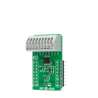
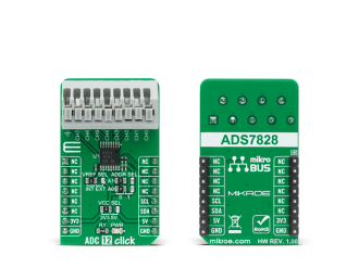
ADC 12 Click is a compact add-on board that contains a fully-featured, general-purpose analog-to-digital converter. This board features the ADS7828, a low-power 12-bit data acquisition device that features a serial I2C interface and an 8-channel multiplexer from Texas Instruments.

No Abuse Reported
  • mikroSDK Library 2.0.0.0
  • Comments (0)
DOWNLOAD LINK RELATED COMPILER CONTAINS
mikroBasic PRO for ARM
  • lib
  • src
  • exa
  • hlp
  • hex
  • sch
  • pcb
  • doc
mikroBasic PRO for AVR
  • lib
  • src
  • exa
  • hlp
  • hex
  • sch
  • pcb
  • doc
mikroBasic PRO for dsPIC30/33 & PIC24
  • lib
  • src
  • exa
  • hlp
  • hex
  • sch
  • pcb
  • doc
mikroBasic PRO for FT90x
  • lib
  • src
  • exa
  • hlp
  • hex
  • sch
  • pcb
  • doc
mikroBasic PRO for PIC
  • lib
  • src
  • exa
  • hlp
  • hex
  • sch
  • pcb
  • doc
mikroBasic PRO for PIC32
  • lib
  • src
  • exa
  • hlp
  • hex
  • sch
  • pcb
  • doc
mikroC PRO for ARM
  • lib
  • src
  • exa
  • hlp
  • hex
  • sch
  • pcb
  • doc
mikroC PRO for AVR
  • lib
  • src
  • exa
  • hlp
  • hex
  • sch
  • pcb
  • doc
mikroC PRO for dsPIC30/33 & PIC24
  • lib
  • src
  • exa
  • hlp
  • hex
  • sch
  • pcb
  • doc
mikroC PRO for FT90x
  • lib
  • src
  • exa
  • hlp
  • hex
  • sch
  • pcb
  • doc
mikroC PRO for PIC
  • lib
  • src
  • exa
  • hlp
  • hex
  • sch
  • pcb
  • doc
mikroC PRO for PIC32
  • lib
  • src
  • exa
  • hlp
  • hex
  • sch
  • pcb
  • doc
mikroPascal PRO for ARM
  • lib
  • src
  • exa
  • hlp
  • hex
  • sch
  • pcb
  • doc
mikroPascal PRO for AVR
  • lib
  • src
  • exa
  • hlp
  • hex
  • sch
  • pcb
  • doc
mikroPascal PRO for dsPIC30/33 & PIC24
  • lib
  • src
  • exa
  • hlp
  • hex
  • sch
  • pcb
  • doc
mikroPascal PRO for FT90x
  • lib
  • src
  • exa
  • hlp
  • hex
  • sch
  • pcb
  • doc
mikroPascal PRO for PIC
  • lib
  • src
  • exa
  • hlp
  • hex
  • sch
  • pcb
  • doc
mikroPascal PRO for PIC32
  • lib
  • src
  • exa
  • hlp
  • hex
  • sch
  • pcb
  • doc

mikroSDK Library Blog

ADC 12 Click

ADC 12 Click

Native view of the ADC 12 Click board.

View full image
ADC 12 Click

ADC 12 Click

Front and back view of the ADC 12 Click board.

View full image

Library Description

The library covers all the necessary functions to control ADC 12 Click board™. User can set or read input mode or power-down mode, read raw adc or voltage and send command to input register or read output.

Key functions:

  • void adc12_send_cmd ( uint8_t cmd_byte ); - Function is used to configure the device.
  • uint16_t adc12_single_ended ( uint8_t chan, uint16_t v_ref ); - Function is used to get raw ADC value.
  • uint16_t adc12_differential ( uint8_t chan, uint16_t v_ref ); - Function is used to get raw ADC value.

Examples description

The application is composed of three sections :

  • System Initialization - Initializes I2C and LOG structures, and start to write log.
  • Application Initialization - Initalizes I2C driver and configures ADC 12 Click board™, enables single-ended inputs, and turns on Internal Reference and ADC.
  • Application Task - This is an example that shows the capabilities of the ADC 12 Click by reading raw value and voltage inputed on channel 0 and displaying data every second.
void application_task ( )
{
    mikrobus_logWrite( "Read Channel 0 raw", _LOG_LINE );
    adc_r = adc12_single_ended ( ADC12_SNGL_END_CH0, ADC12_INT_V_REF_VAL );
    WordToStr( adc_r, log_txt );
    Ltrim( log_txt );
    mikrobus_logWrite( "ADC raw: ", _LOG_TEXT );
    mikrobus_logWrite( log_txt, _LOG_LINE );
    mikrobus_logWrite( "", _LOG_LINE );
    mikrobus_logWrite( "Read Channel 0 voltage", _LOG_LINE );
    adc_v = adc12_single_ended_volt ( ADC12_SNGL_END_CH0, ADC12_INT_V_REF_VAL );
    FloatToStr( adc_v, log_txt );
    Ltrim( log_txt );
    mikrobus_logWrite( "ADC raw: ", _LOG_TEXT );
    mikrobus_logWrite( log_txt, _LOG_TEXT );
    mikrobus_logWrite( "mV", _LOG_LINE );
    mikrobus_logWrite( "------------------------", _LOG_LINE );
    Delay_ms( 1000 );
}

Other mikroE Libraries used in the example:

  • I2C
  • UART
  • Conversions

Additional notes and informations

Depending on the development board you are using, you may need USB UART clickUSB UART 2 click or RS232 click to connect to your PC, for development systems with no UART to USB interface available on the board. The terminal available in all MikroElektronika compilers, or any other terminal application of your choice, can be used to read the message.

ALSO FROM THIS AUTHOR

Stepper 9 Click

0

Stepper 9 Click is a compact add-on board that contains a bipolar stepper motor driver. This board features the TB67S581FNG, a two-phase bipolar stepping motor driver from Toshiba Semiconductor. Fabricated with the BiCD process, it supports a PWM constant-current control drive and steps resolution from full to 1/32 for less motor noise and smoother control. It has a wide operating voltage range of 8.2V to 44V with a maximum output current capacity of 2A, decay modes selection function, protection, and several anomaly detection indicators.

[Learn More]

Haptic click

2

Haptic click carries a Haptic Driver for ERM and LRA vibration motors. The board carries screw terminals for connecting said motors, as well as an audio interface (3.5mm jack). Haptic click communicates with the target MCU through mikroBUSâ„¢ I2C (SCL, SDA), EN (CS) and PWM pins. The board is designed to use either a 3.3V or 5V power supply.

[Learn More]

Headphone AMP 2 Click

0

Headphone AMP 2 Click is a compact add-on board that contains a stereo headphone amplifier. This board features the MAX9723, a stereo DirectDrive headphone amplifier with BassMax, volume control, and I2C from Analog Devices. The amplifier delivers 62mW into a 16Ω load, and features a high 90dB PSRR at 1KHz and a low 0.006% THD+N. It also features an integrated 32-level volume control, Click-and-pop suppression, ±8kV HBM ESD-protected headphone outputs, short-circuit and thermal-overload protection, and more.

[Learn More]
Close menu