
We strongly encourage users to use Package manager for sharing their code on Libstock website, because it boosts your efficiency and leaves the end user with no room for error. [more info]

Rating:
Author: MIKROE
Last Updated: 2016-02-18
Package Version: 1.0.0.0
Example: 1.0.0.0
Category: USB
Downloaded: 7289 times
Followed by: 2 users
License: MIT license
This is a sample program which demonstrates the use of USB SPI click This device accepts commands from SPI Terminal and sends appropriate bytes via SPI interface. It is very desirable tool for designing SPI slave devices such as sensors...
Do you want to subscribe in order to receive notifications regarding "USB SPI click - Example" changes.
Do you want to unsubscribe in order to stop receiving notifications regarding "USB SPI click - Example" changes.
Do you want to report abuse regarding "USB SPI click - Example".
| DOWNLOAD LINK | RELATED COMPILER | CONTAINS |
|---|---|---|
| 1344525015_usb_spi_click____mikroc_pic.rar [79.43KB] | mikroC PRO for PIC |
|
| 1344525033_usb_spi_click____mikrobasic_pic.rar [79.51KB] | mikroBasic PRO for PIC |
|
| 1344525046_usb_spi_click____mikropascal_pic.rar [79.55KB] | mikroPascal PRO for PIC |
|

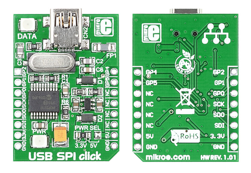
USB SPI click is a compact and easy solution for adding SPI serial communication via USB cable. It features MCP2210 USB-to-SPI protocol converter with GPIO as well as USB MINI B connector. USB SPI Click communicates with target board via SPI interface as a master device.
PIC examples are written for :
- EasyPIC7 - PIC18F45K22
MCP2210 should be controlled with SPI Terminal application. MCP2210 SPI Terminal and MCP2210 Utility applications can be downloaded from the following links:

MCP2210 should be configured before use. Proper settings for this example are shown on the image.
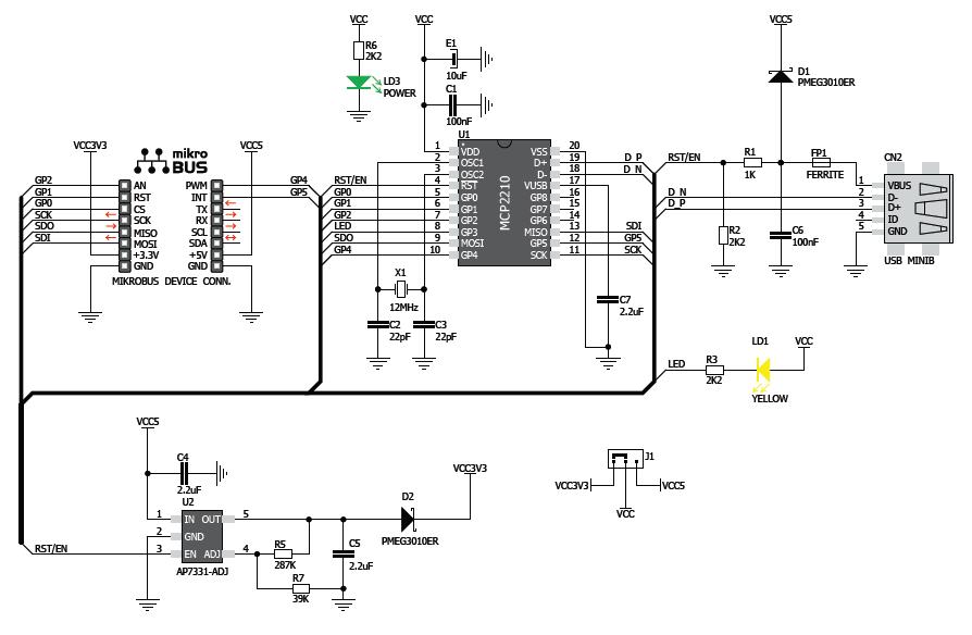
View full imageAny of the GP (General Purpose) pins can be used as chip select. User should select appropriate GP pin according to his own connections. GP pins are clearly marked on USB SPI click board and schematics.
Also user can define SPI speed and total number of bytes to transmit. In TX Data and RX Data windows are shown transmitted and received bytes.
Hex mode box should be checked if user want to preview data as hexadecimal.


