We strongly encourage users to use Package manager for sharing their code on Libstock website, because it boosts your efficiency and leaves the end user with no room for error. [more info]

Rating:
Author: VCC
Last Updated: 2021-02-03
Package Version: 1.0.0.0
Example: 1.0.0.0
Category: Audio recording
Downloaded: 153 times
Not followed.
License: MIT license
This is an example of a Peak Programme Meter with 2x16 LEDs. The scale is linear in volts, not dB. The integration time is much shorter than the fall time. It is useful to indicate signal clipping.
This example follows no standard, it is for demonstration purposes only.
Do you want to subscribe in order to receive notifications regarding "Peak Programme Meter with LEDs" changes.
Do you want to unsubscribe in order to stop receiving notifications regarding "Peak Programme Meter with LEDs" changes.
Do you want to report abuse regarding "Peak Programme Meter with LEDs".
| DOWNLOAD LINK | RELATED COMPILER | CONTAINS |
|---|---|---|
| 1612344780_peak_programme_m_mikropascal_pic.zip [6.83KB] | mikroPascal PRO for PIC |
|
Peak programme meter with PIC18F26K22.
The presented example uses the internal DAC of the PIC18F26K22, as voltage ref to its ADC and is set somwhere below 2.5V. This was selected for an analogue input circuit (a half-wave precision rectifier), powered at +/- 2.5V (not included in the current presented schematic).
The first part of the video shows the actual PPM, while the second part shows a a test app.
Watch on YouTube

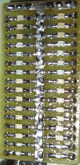
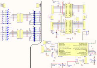
PIC18F26K22 with two MCP23S18 port expanders. In the current implementation, the LEDs are actually on a module board, for easy connectivity.
View full image