
We strongly encourage users to use Package manager for sharing their code on Libstock website, because it boosts your efficiency and leaves the end user with no room for error. [more info]

Rating:
Author: MIKROE
Last Updated: 2016-02-18
Package Version: 1.0.0.0
Category: GSM / GPRS
Downloaded: 6845 times
Followed by: 6 users
License: MIT license
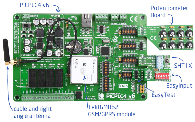
Using PICPLC4 v6, TelitGM862 GSM/GPRS module, Potentiometer Board, SHT1X Temperature and Humidity Sensor, and EasyInput Boards, we have created Smart SMS relay Control Station and an example which you can adjust according to your needs.
Do you want to subscribe in order to receive notifications regarding "Smart SMS Relay Control Station" changes.
Do you want to unsubscribe in order to stop receiving notifications regarding "Smart SMS Relay Control Station" changes.
Do you want to report abuse regarding "Smart SMS Relay Control Station".
| DOWNLOAD LINK | RELATED COMPILER | CONTAINS |
|---|---|---|
| 1313658775_smart_sms_relay_.zip [1.04MB] | mikroC PRO for PIC |
|
| 1313658801_smart_sms_relay_.zip [1.04MB] | mikroBasic PRO for PIC |
|
| 1313658825_smart_sms_relay_.zip [1.04MB] | mikroPascal PRO for PIC |
|

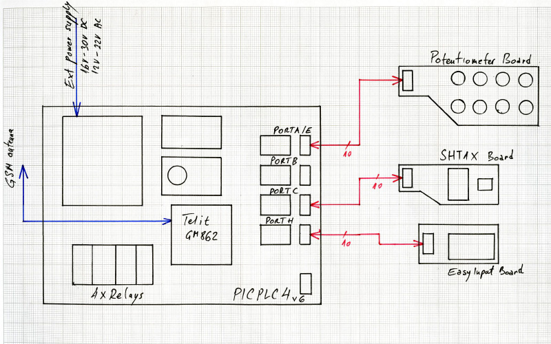
Smart SMS Relay Control Station connections
View full imageRemotely controlled and monitored systems are becoming increasingly popular by the day. Smart automata, such as SMS vending machines or parking ticket payment stations became part of our everyday lives. We are presenting you with a fantastic and most useful project, which can have dozens of great applications. Using PICPLC4 v6, TelitGM862 GSM/GPRS module, Potentiometer Board, SHT1X Temperature and Humidity Sensor, and EasyInput Boards, we have created Smart SMS relay Control Station and an example which you can adjust according to your needs. What it does is basically this:
Program is triggered by incoming SMS message. It sends information about current automata state, and can also be ordered to turn on/off four available relays.
Project has numerous applications. We only suggest several:
We are sure that you will find much more possible applications. Don’t hesitate to send us photos of what you have built using this project kit.

Source code of this project is provided for free, so you can modify it to suit your needs. Since PIC18F87J60 comes preprogrammed with free UART Bootloader, you won’t have to spend a dollar more on external programmers. You can use both on-board UART connector or additional USB-UART board if you do not have RS-232 connector available on your computer.


