TOP Contributors

  1. MIKROE (2784 codes)
  2. Alcides Ramos (404 codes)
  3. Shawon Shahryiar (307 codes)
  4. jm_palomino (133 codes)
  5. Bugz Bensce (97 codes)
  6. S P (73 codes)
  7. dany (71 codes)
  8. MikroBUS.NET Team (35 codes)
  9. NART SCHINACKOW (34 codes)
  10. Armstrong Subero (27 codes)

Most Downloaded

  1. Timer Calculator (141112 times)
  2. FAT32 Library (73906 times)
  3. Network Ethernet Library (58554 times)
  4. USB Device Library (48725 times)
  5. Network WiFi Library (44376 times)
  6. FT800 Library (43977 times)
  7. GSM click (30721 times)
  8. mikroSDK (29478 times)
  9. PID Library (27304 times)
  10. microSD click (27132 times)
Libstock prefers package manager

Package Manager

We strongly encourage users to use Package manager for sharing their code on Libstock website, because it boosts your efficiency and leaves the end user with no room for error. [more info]

< Back
mikroSDK Library

ADC 2 click

Rating:

5

Author: MIKROE

Last Updated: 2019-03-26

Package Version: 1.0.0.1

mikroSDK Library: 1.0.0.0

Category: ADC

Downloaded: 6175 times

Followed by: 4 users

License: MIT license  

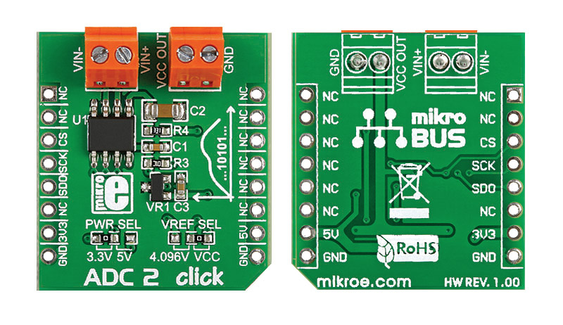
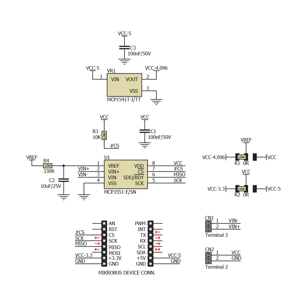
ADC 2 click carries MCP3551/3, which is a 22-bit ADC with automatic internal offset and gain calibration. This high precision analog-to-digital converter has total unadjusted error of less than 10 ppm, and low-output noise of 2.5 µV RMS. ADC 2 click communicates with the target board through mikroBUS CS, CSK and MISO lines.

No Abuse Reported

Do you want to subscribe in order to receive notifications regarding "ADC 2 click" changes.

Do you want to unsubscribe in order to stop receiving notifications regarding "ADC 2 click" changes.

Do you want to report abuse regarding "ADC 2 click".

  • mikroSDK Library 2.0.0.0
  • Comments (0)
DOWNLOAD LINK RELATED COMPILER CONTAINS
mikroBasic PRO for ARM
  • lib
  • src
  • exa
  • hlp
  • hex
  • sch
  • pcb
  • doc
mikroBasic PRO for AVR
  • lib
  • src
  • exa
  • hlp
  • hex
  • sch
  • pcb
  • doc
mikroBasic PRO for dsPIC30/33 & PIC24
  • lib
  • src
  • exa
  • hlp
  • hex
  • sch
  • pcb
  • doc
mikroBasic PRO for FT90x
  • lib
  • src
  • exa
  • hlp
  • hex
  • sch
  • pcb
  • doc
mikroBasic PRO for PIC
  • lib
  • src
  • exa
  • hlp
  • hex
  • sch
  • pcb
  • doc
mikroBasic PRO for PIC32
  • lib
  • src
  • exa
  • hlp
  • hex
  • sch
  • pcb
  • doc
mikroC PRO for ARM
  • lib
  • src
  • exa
  • hlp
  • hex
  • sch
  • pcb
  • doc
mikroC PRO for AVR
  • lib
  • src
  • exa
  • hlp
  • hex
  • sch
  • pcb
  • doc
mikroC PRO for dsPIC30/33 & PIC24
  • lib
  • src
  • exa
  • hlp
  • hex
  • sch
  • pcb
  • doc
mikroC PRO for FT90x
  • lib
  • src
  • exa
  • hlp
  • hex
  • sch
  • pcb
  • doc
mikroC PRO for PIC
  • lib
  • src
  • exa
  • hlp
  • hex
  • sch
  • pcb
  • doc
mikroC PRO for PIC32
  • lib
  • src
  • exa
  • hlp
  • hex
  • sch
  • pcb
  • doc
mikroPascal PRO for ARM
  • lib
  • src
  • exa
  • hlp
  • hex
  • sch
  • pcb
  • doc
mikroPascal PRO for AVR
  • lib
  • src
  • exa
  • hlp
  • hex
  • sch
  • pcb
  • doc
mikroPascal PRO for dsPIC30/33 & PIC24
  • lib
  • src
  • exa
  • hlp
  • hex
  • sch
  • pcb
  • doc
mikroPascal PRO for FT90x
  • lib
  • src
  • exa
  • hlp
  • hex
  • sch
  • pcb
  • doc
mikroPascal PRO for PIC
  • lib
  • src
  • exa
  • hlp
  • hex
  • sch
  • pcb
  • doc
mikroPascal PRO for PIC32
  • lib
  • src
  • exa
  • hlp
  • hex
  • sch
  • pcb
  • doc

mikroSDK Library Blog

ADC 2 click board

ADC 2 click board

Front and back side appearance of the ADC 2 Click Board.

View full image

Library Description

The library covers all the necessary functions that enables the usage of the ADC 2 click board.
It initializes and defines the SPI driver and drivers that offer functions for reading digital data
and for checking overflow states.

Key functions:

  • uint32_t adc2_adcValueRead(); -  Function is used to read specific data from ADC convertor.
  • uint8_t adc2_checkOverLow();-   Function is used to check overflow low state.
  • uint8_t adc2_checkOverHigh(); -   Function is used to check overflow high state.

Examples Description

The application is composed of three sections:

  • System Initialization - Initializes SPI module, LOG structure, sets CS pin as output.
  • Application Initialization - Initalizes SPI driver and makes an initial log.
  • Application Task - (code snippet) This is an example that shows the capabilities of the ADC 2 click by reading ad conversion.
void applicationTask()
{
    adcVal = adc2_adcValueRead();
    
    LongToStr( adcVal, logTxt );
    Ltrim( logTxt );
    mikrobus_logWrite( "Value : ", _LOG_TEXT );
    mikrobus_logWrite( logTxt, _LOG_LINE );
    mikrobus_logWrite( "------------------", _LOG_LINE );
    Delay_ms( 1000 );
}  

Other mikroE Libraries used in the example:

  • SPI
  • UART
  • Conversions

Additional notes and informations

Depending on the development board you are using, you may need USB UART clickUSB UART 2 click or RS232 click to connect to your PC, for development systems with no UART to USB interface available on the board. The terminal available in all MikroElektronika compilers, or any other terminal application of your choice, can be used to read the message

ADC 2 click board schematic

ADC 2 click board schematic

Schematics of the ADC 2 Click Board

View full image

ALSO FROM THIS AUTHOR

RMS to DC click

7

RMS to DC click is a Click board that is used to convert the RMS of the input signal into a DC voltage, with a value directly readable over the I2C interface. The Click board is equipped with the LTC1968, an RMS-to-DC converter IC, which outputs an analog voltage depending on the RMS value of the input signal.

[Learn More]

Clock Gen 2 click

5

Clock Gen 2 click is an accurate square wave generator that can generate a clock signal in the range from 260kHz to 66.6MHz.

[Learn More]

Oximeter 5 Click

0

Oximeter 5 Click is a compact add-on board suitable for measuring blood oxygen saturation. This board features the MAX30102, integrated pulse oximetry, and heart-rate monitor module from Analog Devices. The MAX30102 includes internal LEDs, photodetectors, optical elements, and low-noise electronics with ambient light rejection. It operates on a single 1.8V power supply acquired from both mikroBUS™ power rails for the internal LEDs, communicating through a standard I2C compatible interface. The MAX30102 can be shut down through software with zero standby current, allowing the power rails to remain powered at all times.

[Learn More]