TOP Contributors

  1. MIKROE (2784 codes)
  2. Alcides Ramos (405 codes)
  3. Shawon Shahryiar (307 codes)
  4. jm_palomino (133 codes)
  5. Bugz Bensce (97 codes)
  6. S P (73 codes)
  7. dany (71 codes)
  8. MikroBUS.NET Team (35 codes)
  9. NART SCHINACKOW (34 codes)
  10. Armstrong Subero (27 codes)

Most Downloaded

  1. Timer Calculator (141274 times)
  2. FAT32 Library (74088 times)
  3. Network Ethernet Library (58715 times)
  4. USB Device Library (48823 times)
  5. Network WiFi Library (44525 times)
  6. FT800 Library (44072 times)
  7. GSM click (30803 times)
  8. mikroSDK (29654 times)
  9. PID Library (27355 times)
  10. microSD click (27251 times)
Libstock prefers package manager

Package Manager

We strongly encourage users to use Package manager for sharing their code on Libstock website, because it boosts your efficiency and leaves the end user with no room for error. [more info]

< Back
mikroSDK Library

Heart rate click

Rating:

8

Author: MIKROE

Last Updated: 2018-03-12

Package Version: 1.0.0.1

mikroSDK Library: 1.0.0.0

Category: Biometrics

Downloaded: 11336 times

Followed by: 3 users

License: MIT license  

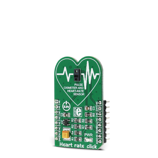
Heart Rate click carries a MAX30100 integrated pulse oximetry and heart-rate sensor. It’s an optical sensor that derives its readings from emitting two wavelengths of light from two LEDs, then measuring the absorbance of pulsing blood through a photodetector. Uses 3.3V power supply.

No Abuse Reported

Do you want to subscribe in order to receive notifications regarding "Heart rate click" changes.

Do you want to unsubscribe in order to stop receiving notifications regarding "Heart rate click" changes.

Do you want to report abuse regarding "Heart rate click".

  • mikroSDK Library 2.0.0.0
  • Comments (3)
DOWNLOAD LINK RELATED COMPILER CONTAINS
mikroBasic PRO for ARM
  • lib
  • src
  • exa
  • hlp
  • hex
  • sch
  • pcb
  • doc
mikroBasic PRO for AVR
  • lib
  • src
  • exa
  • hlp
  • hex
  • sch
  • pcb
  • doc
mikroBasic PRO for dsPIC30/33 & PIC24
  • lib
  • src
  • exa
  • hlp
  • hex
  • sch
  • pcb
  • doc
mikroBasic PRO for FT90x
  • lib
  • src
  • exa
  • hlp
  • hex
  • sch
  • pcb
  • doc
mikroBasic PRO for PIC
  • lib
  • src
  • exa
  • hlp
  • hex
  • sch
  • pcb
  • doc
mikroBasic PRO for PIC32
  • lib
  • src
  • exa
  • hlp
  • hex
  • sch
  • pcb
  • doc
mikroC PRO for ARM
  • lib
  • src
  • exa
  • hlp
  • hex
  • sch
  • pcb
  • doc
mikroC PRO for AVR
  • lib
  • src
  • exa
  • hlp
  • hex
  • sch
  • pcb
  • doc
mikroC PRO for dsPIC30/33 & PIC24
  • lib
  • src
  • exa
  • hlp
  • hex
  • sch
  • pcb
  • doc
mikroC PRO for FT90x
  • lib
  • src
  • exa
  • hlp
  • hex
  • sch
  • pcb
  • doc
mikroC PRO for PIC
  • lib
  • src
  • exa
  • hlp
  • hex
  • sch
  • pcb
  • doc
mikroC PRO for PIC32
  • lib
  • src
  • exa
  • hlp
  • hex
  • sch
  • pcb
  • doc
mikroPascal PRO for ARM
  • lib
  • src
  • exa
  • hlp
  • hex
  • sch
  • pcb
  • doc
mikroPascal PRO for AVR
  • lib
  • src
  • exa
  • hlp
  • hex
  • sch
  • pcb
  • doc
mikroPascal PRO for dsPIC30/33 & PIC24
  • lib
  • src
  • exa
  • hlp
  • hex
  • sch
  • pcb
  • doc
mikroPascal PRO for FT90x
  • lib
  • src
  • exa
  • hlp
  • hex
  • sch
  • pcb
  • doc
mikroPascal PRO for PIC
  • lib
  • src
  • exa
  • hlp
  • hex
  • sch
  • pcb
  • doc
mikroPascal PRO for PIC32
  • lib
  • src
  • exa
  • hlp
  • hex
  • sch
  • pcb
  • doc

mikroSDK Library Blog

Heart rate click

Heart rate click

Native view of the Heart rate click board.

View full image
Heart Rate click board

Heart Rate click board

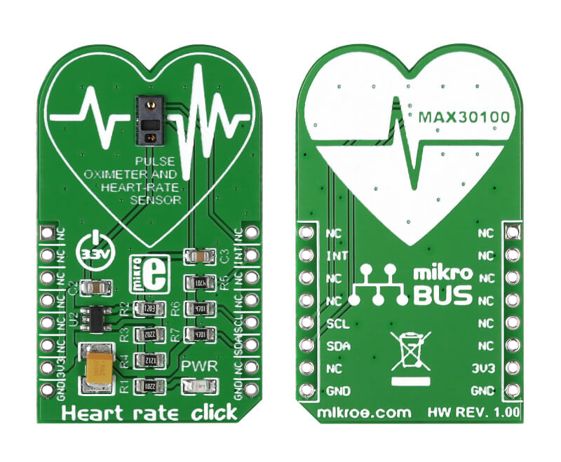
Front and back side appearance of the Heart Rate click board.

View full image

Library Description Key functions:

  • uint8_t heartrate_readIrRed(uint16_t *ir_buff, uint16_t *red_buff ); - This function reads IR and RED values.
  • void heartrate_init(); - This function restarts and initializes the Heartrate chip.
  • uint8_t heartrateDataReady() - This function checks if the data is ready for reading.

Examples Description

  • System Initialization - Initializes GPIO INT as the input pin, I2C, and UART for logging.
  • Application Initialization - Initializes heartrate driver and Click board™.
  • Application Task - reading the value from both Ir and Red diode displaying their average values.
void applicationTask()
{
 if (heartrateDataReady()) 
 {
 sample_num = heartrate_readIrRed( &ir_buff, &red_buff ); 

 if ( sample_num >= 1 )
 {
 ir_average = 0;
 red_average = 0;

 for ( counter1 = 0; counter1 < sample_num; counter1++ )
 {
 ir_average += ir_buff[counter1];
 red_average += red_buff[counter1];
 } 
 ir_average /= sample_num;
 red_average /= sample_num;
 counter2++;

 if(counter2 > 100)
 {
 mikrobus_logWrite("Average value of Red LED sensor per 100 samples:",
_LOG_TEXT);
 WordToStr(red_average, text);
 mikrobus_logWrite(text,_LOG_LINE);
 mikrobus_logWrite("Average value of IR LED sensor per 100 samples:",
_LOG_TEXT);
 WordToStr(ir_average, text);
 mikrobus_logWrite(text,_LOG_LINE);
 counter2 = 0;
 }
 }
 }
}

Other mikroE Libraries used in the example:

  • UART
  • Conversions
  • I2C

Additional notes and information Depending on the development board you are using, you may need USB UART click,  USB UART 2 click or RS232 click to connect to your PC, for development systems with no UART to USB interface available on the board. The terminal available in all MikroElektronika compilers, or any other terminal application of your choice, can be used to read the message.  


ALSO FROM THIS AUTHOR

DAC 12 Click

0

DAC 12 Click is a compact add-on board that contains a highly accurate digital-to-analog converter. This board features the DAC60508, a general-purpose octal 12-bit analog voltage-output DAC from Texas Instruments. It includes a 2.5V, 5ppm/°C internal reference, eliminating the need for an external precision reference in most applications, and supports the SPI serial interface, which operates at clock rates up to 40MHz. A user interface-selectable gain configuration provides full-scale output voltages of 1.25V, 2.5V, or 5 V. This Click board™ represents an excellent choice for digital gain and offset adjustment applications, programmable voltage, and current sources, programmable reference, and many more.

[Learn More]

GPS click

5

Simple example which demonstrates usage of the GPS Click board with uBlox module. <br>It displays a map of the world on the Glcd and shows the location of the GPS module on it.

[Learn More]

Multi Stepper TB67S269 Click

0

Multi Stepper Click is a compact add-on board that contains a bipolar stepper motor driver. This board features the TB67S269FTG, CLOCK-in controlled bipolar stepping motor driver from Toshiba Semiconductor. It supports a PWM constant-current control drive and allows from full-step up to 1/32 steps resolution for less motor noise and smoother control. It has a wide operating voltage range of 10V to 47V with an output current capacity of 1.4A in addition to several built-in error detection circuits.

[Learn More]