TOP Contributors

  1. MIKROE (2784 codes)
  2. Alcides Ramos (404 codes)
  3. Shawon Shahryiar (307 codes)
  4. jm_palomino (133 codes)
  5. Bugz Bensce (97 codes)
  6. S P (73 codes)
  7. dany (71 codes)
  8. MikroBUS.NET Team (35 codes)
  9. NART SCHINACKOW (34 codes)
  10. Armstrong Subero (27 codes)

Most Downloaded

  1. Timer Calculator (141107 times)
  2. FAT32 Library (73898 times)
  3. Network Ethernet Library (58547 times)
  4. USB Device Library (48723 times)
  5. Network WiFi Library (44371 times)
  6. FT800 Library (43971 times)
  7. GSM click (30717 times)
  8. mikroSDK (29471 times)
  9. PID Library (27299 times)
  10. microSD click (27092 times)
Libstock prefers package manager

Package Manager

We strongly encourage users to use Package manager for sharing their code on Libstock website, because it boosts your efficiency and leaves the end user with no room for error. [more info]

< Back
mikroSDK Library

Timer click

Rating:

1

Author: MIKROE

Last Updated: 2019-03-14

Package Version: 1.0.0.1

mikroSDK Library: 1.0.0.0

Category: RTC

Downloaded: 5457 times

Not followed.

License: MIT license  

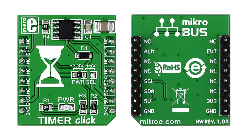
Timer click is a mikroBUS add-on board with Maxim’s DS1682 total elapsed time recorder. It holds an elapsed time counter (ETC) in conjunction with the ALARM pin. The alarm flag is one time programmable. The board communicates through I2C interface, with two additional pins: ALARM and EVENT. It uses either a 3.3V or a 5V power supply only.

No Abuse Reported

Do you want to subscribe in order to receive notifications regarding "Timer click" changes.

Do you want to unsubscribe in order to stop receiving notifications regarding "Timer click" changes.

Do you want to report abuse regarding "Timer click".

  • mikroSDK Library 2.0.0.0
  • Comments (0)
DOWNLOAD LINK RELATED COMPILER CONTAINS
mikroBasic PRO for ARM
  • lib
  • src
  • exa
  • hlp
  • hex
  • sch
  • pcb
  • doc
mikroBasic PRO for AVR
  • lib
  • src
  • exa
  • hlp
  • hex
  • sch
  • pcb
  • doc
mikroBasic PRO for dsPIC30/33 & PIC24
  • lib
  • src
  • exa
  • hlp
  • hex
  • sch
  • pcb
  • doc
mikroBasic PRO for FT90x
  • lib
  • src
  • exa
  • hlp
  • hex
  • sch
  • pcb
  • doc
mikroBasic PRO for PIC
  • lib
  • src
  • exa
  • hlp
  • hex
  • sch
  • pcb
  • doc
mikroBasic PRO for PIC32
  • lib
  • src
  • exa
  • hlp
  • hex
  • sch
  • pcb
  • doc
mikroC PRO for ARM
  • lib
  • src
  • exa
  • hlp
  • hex
  • sch
  • pcb
  • doc
mikroC PRO for AVR
  • lib
  • src
  • exa
  • hlp
  • hex
  • sch
  • pcb
  • doc
mikroC PRO for dsPIC30/33 & PIC24
  • lib
  • src
  • exa
  • hlp
  • hex
  • sch
  • pcb
  • doc
mikroC PRO for FT90x
  • lib
  • src
  • exa
  • hlp
  • hex
  • sch
  • pcb
  • doc
mikroC PRO for PIC
  • lib
  • src
  • exa
  • hlp
  • hex
  • sch
  • pcb
  • doc
mikroC PRO for PIC32
  • lib
  • src
  • exa
  • hlp
  • hex
  • sch
  • pcb
  • doc
mikroPascal PRO for ARM
  • lib
  • src
  • exa
  • hlp
  • hex
  • sch
  • pcb
  • doc
mikroPascal PRO for AVR
  • lib
  • src
  • exa
  • hlp
  • hex
  • sch
  • pcb
  • doc
mikroPascal PRO for dsPIC30/33 & PIC24
  • lib
  • src
  • exa
  • hlp
  • hex
  • sch
  • pcb
  • doc
mikroPascal PRO for FT90x
  • lib
  • src
  • exa
  • hlp
  • hex
  • sch
  • pcb
  • doc
mikroPascal PRO for PIC
  • lib
  • src
  • exa
  • hlp
  • hex
  • sch
  • pcb
  • doc
mikroPascal PRO for PIC32
  • lib
  • src
  • exa
  • hlp
  • hex
  • sch
  • pcb
  • doc

mikroSDK Library Blog

Timer Click

Timer Click

Front and back view of the Timer Click board

View full image

Library Description

The library covers all the necessary functions to control Timer Click board. Timer click communicates with the target board via I2C protocol. This library contains drivers to write and reads data from DS1682 total elapsed time recorder, the function for set/gets ETC, EC, alarm seconds, for reading/write EEPROM memory, etc.

Key functions:

  • void timer_setETCData( uint32_t etcValue ) - Set elapsed time counter (ETC) data function.
  • void timer_getTime( uint16_t *timeDays, uint8_t *timeHours, uint8_t *timeMinutes, uint8_t *timeSeconds ) - Get elapsed time counter (ETC) time function.
  • void timer_setAlarmSeconds( uint32_t alarmSeconds ) - Set alarm seconds function.

Examples description

The application is composed of three sections:

  • System Initialization - Initializes GPIO, I2C and LOG structures, sets RST pin as output and INT pin as input.
  • Application Initialization -  Initialization driver enables - I2C, soft reset, sets ETC and EC start ( seconds ), hardware reset and start write log.
  • Application Task - (code snippet) This is an example which demonstrates the use of Timer Click board. Timer Click communicates with register via I2C by writing to register and read from the register, display time ( days, hours, minutes and seconds ) which we received reading from the target register address of DS1682 total elapsed time recorder. Results are being sent to the Usart Terminal where you can track their changes. All data logs write on USB uart changes for every 1 sec.
void applicationTask() 
{
    timer_getTime( &timeDays, &timeHours, &timeMinutes, &timeSeconds );
    
    if ( timeSecondsNew != timeSeconds )
    {
        mikrobus_logWrite( " ", _LOG_TEXT );
        displayLogUart( timeDays );
        mikrobus_logWrite( " days ", _LOG_TEXT );

        displayLogUart( timeHours );
        mikrobus_logWrite( ":", _LOG_TEXT );

        displayLogUart( timeMinutes ); 
        mikrobus_logWrite( ":", _LOG_TEXT );

        displayLogUart( timeSeconds );  
        mikrobus_logWrite( "", _LOG_LINE );
        mikrobus_logWrite( "------------------", _LOG_LINE );

        timeSecondsNew = timeSeconds;
    }
    
    Delay_1ms();
}

Additional Functions :

  • void displayLogUart( uint8_t value ) - Write the value of time or date as a two-digit number.

Other mikroE Libraries used in the example:

  • I2C
  • UART​
  • Conversion

Additional notes and informations

Depending on the development board you are using, you may need USB UART clickUSB UART 2 click or RS232 click to connect to your PC, for development systems with no UART to USB interface available on the board. The terminal available in all MikroElektronika compilers, or any other terminal application of your choice, can be used to read the message

ALSO FROM THIS AUTHOR

MCP251863 Click

0

MCP251863 Click is a compact add-on board representing a complete CAN solution used as a control node in a CAN network. This board features the MCP251863, IC representing a compact solution with a controller and a transceiver in one package, the MCP2518FD and ATA6563 from Microchip. The ATA6563, a low-level physical layer IC (PHY), provides a physical connection with the CAN bus itself, while the CAN controller MCP2518FD represents an interface between the MCU and the PHY. It features three operating modes with dedicated fail-safe features, remote wake-up via CAN, and ideally passive behavior when powered off on the CAN bus. This Click board™ is suitable for developing a wide range of automotive diagnostic applications, even on MCUs that don’t support CAN interface.

[Learn More]

Slider click

5

Slider click uses SPI bus communication to converts analog input voltage (VCC) to digital output value and shows this result on LED and USB UART terminal. Value of analog voltage depends on the slider position.

[Learn More]

DAC 2 Click

5

DAC 2 click carries LTC2601CDD, a 16-bit digital-to-analog converter, along with voltage output screw terminals.The click board communicates with the target MCU through the mikroBUS SPI interface (MISO, MOSI pins) with clock rates up to 50MHz.

[Learn More]