TOP Contributors

  1. MIKROE (2784 codes)
  2. Alcides Ramos (387 codes)
  3. Shawon Shahryiar (307 codes)
  4. jm_palomino (120 codes)
  5. Bugz Bensce (97 codes)
  6. S P (73 codes)
  7. dany (71 codes)
  8. MikroBUS.NET Team (35 codes)
  9. NART SCHINACKOW (34 codes)
  10. Armstrong Subero (27 codes)

Most Downloaded

  1. Timer Calculator (140169 times)
  2. FAT32 Library (72625 times)
  3. Network Ethernet Library (57645 times)
  4. USB Device Library (47958 times)
  5. Network WiFi Library (43555 times)
  6. FT800 Library (42942 times)
  7. GSM click (30141 times)
  8. mikroSDK (28672 times)
  9. PID Library (27058 times)
  10. microSD click (26553 times)
Libstock prefers package manager

Package Manager

We strongly encourage users to use Package manager for sharing their code on Libstock website, because it boosts your efficiency and leaves the end user with no room for error. [more info]

< Back
mikroSDK Library

Heart rate 3 click

Rating:

4

Author: MIKROE

Last Updated: 2019-07-30

Package Version: 1.0.0.1

mikroSDK Library: 1.0.0.0

Category: Biometrics

Downloaded: 5684 times

Not followed.

License: MIT license  

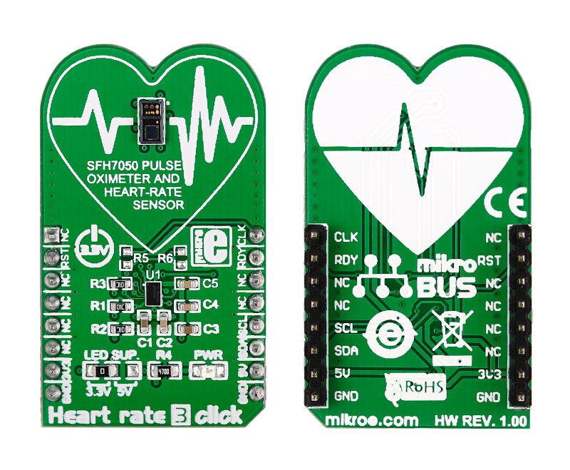
Heart rate 3 click is a mikroBUS add-on board whose functionality is determined by two components: an OSRAM’s SFH7050 pulse oximetry and heart rate monitoring module, and a TI AFE4404 (analong-front-end) IC specialized for bio-sensing.


No Abuse Reported

Do you want to subscribe in order to receive notifications regarding "Heart rate 3 click" changes.

Do you want to unsubscribe in order to stop receiving notifications regarding "Heart rate 3 click" changes.

Do you want to report abuse regarding "Heart rate 3 click".

  • mikroSDK Library 2.0.0.0
  • Comments (2)
DOWNLOAD LINK RELATED COMPILER CONTAINS
mikroBasic PRO for ARM
  • lib
  • src
  • exa
  • hlp
  • hex
  • sch
  • pcb
  • doc
mikroBasic PRO for AVR
  • lib
  • src
  • exa
  • hlp
  • hex
  • sch
  • pcb
  • doc
mikroBasic PRO for dsPIC30/33 & PIC24
  • lib
  • src
  • exa
  • hlp
  • hex
  • sch
  • pcb
  • doc
mikroBasic PRO for FT90x
  • lib
  • src
  • exa
  • hlp
  • hex
  • sch
  • pcb
  • doc
mikroBasic PRO for PIC
  • lib
  • src
  • exa
  • hlp
  • hex
  • sch
  • pcb
  • doc
mikroBasic PRO for PIC32
  • lib
  • src
  • exa
  • hlp
  • hex
  • sch
  • pcb
  • doc
mikroC PRO for ARM
  • lib
  • src
  • exa
  • hlp
  • hex
  • sch
  • pcb
  • doc
mikroC PRO for AVR
  • lib
  • src
  • exa
  • hlp
  • hex
  • sch
  • pcb
  • doc
mikroC PRO for dsPIC30/33 & PIC24
  • lib
  • src
  • exa
  • hlp
  • hex
  • sch
  • pcb
  • doc
mikroC PRO for FT90x
  • lib
  • src
  • exa
  • hlp
  • hex
  • sch
  • pcb
  • doc
mikroC PRO for PIC
  • lib
  • src
  • exa
  • hlp
  • hex
  • sch
  • pcb
  • doc
mikroC PRO for PIC32
  • lib
  • src
  • exa
  • hlp
  • hex
  • sch
  • pcb
  • doc
mikroPascal PRO for ARM
  • lib
  • src
  • exa
  • hlp
  • hex
  • sch
  • pcb
  • doc
mikroPascal PRO for AVR
  • lib
  • src
  • exa
  • hlp
  • hex
  • sch
  • pcb
  • doc
mikroPascal PRO for dsPIC30/33 & PIC24
  • lib
  • src
  • exa
  • hlp
  • hex
  • sch
  • pcb
  • doc
mikroPascal PRO for FT90x
  • lib
  • src
  • exa
  • hlp
  • hex
  • sch
  • pcb
  • doc
mikroPascal PRO for PIC
  • lib
  • src
  • exa
  • hlp
  • hex
  • sch
  • pcb
  • doc
mikroPascal PRO for PIC32
  • lib
  • src
  • exa
  • hlp
  • hex
  • sch
  • pcb
  • doc

mikroSDK Library Blog

Heart rate 3 click back and front pictures.

Heart rate 3 click back and front pictures.

Front and back pictures of Heart rate 3 click.

View full image

Library Description

The library covers all the necessary functions that enables the usage of the Heart rate 4 Click board. It initializes and defines the I2C bus driver and drivers that offer a choice for writing and reading and setting a new value.

Key functions:

  • void heartrate3_defaultConfig() - Function is used to apply the default configuration.
  • uint32_t heartrate3_readLed2ValReg() - Function is used to read from LED2VAL register.
  • uint32_t heartrate3_readAled2ValReg() - Function is used to read from ALED2VAL register.

Examples description

The application is composed of three sections :

  • System Initialization - Initializes I2C module, LOG and GPIO structures, sets INT pin as input and RST and PWM pins as output.
  • Application Initialization - Initalizes I2C driver, applies default settings, and makes an initial log.
  • Application Task - This example demonstrates the use of Heart rate 3 board. It is set in default mode, and reads reflected red, green and ir values and displays the results on USART terminal.
void applicationTask()
{
    led2Val = heartrate3_readLed2ValReg();
    LongToStr( led2Val, logTxt );
    mikrobus_logWrite( logTxt, _LOG_LINE );

    aled2Val = heartrate3_readAled2ValReg();
    LongToStr( aled2Val, logTxt );
    mikrobus_logWrite( logTxt, _LOG_LINE );

    led1Val = heartrate3_readLed1ValReg();
    LongToStr( led1Val, logTxt );
    mikrobus_logWrite( logTxt, _LOG_LINE );

    aled1Val = heartrate3_readAled1ValReg();
    LongToStr( aled1Val, logTxt );
    mikrobus_logWrite( logTxt, _LOG_LINE );

    led2Aled2Val = heartrate3_readLed2Aled2ValReg();
    LongToStr( led2Aled2Val, logTxt );
    mikrobus_logWrite( logTxt, _LOG_LINE );

    led1Aled1Val = heartrate3_readLed1Aled1ValReg();
    LongToStr( led1Aled1Val, logTxt );
    mikrobus_logWrite( logTxt, _LOG_LINE );

    mikrobus_logWrite( "----------------------", _LOG_LINE );
    Delay_ms( 100 );
}

Other mikroE Libraries used in the example:

  • I2C
  • UART
  • Conversions

Additional notes and informations

Depending on the development board you are using, you may need USB UART clickUSB UART 2 click or RS232 click to connect to your PC, for development systems with no UART to USB interface available on the board. The terminal available in all MikroElektronika compilers, or any other terminal application of your choice, can be used to read the message.

Heart rate 3 click

Heart rate 3 click

Heart rate 3 click schematic.

View full image

ALSO FROM THIS AUTHOR

UART 1-Wire Click

0

UART 1-Wire Click is used to convert standard UART or RS232 signals into 1-Wire® signals. Apart from other features such as the slew rate control for larger 1-Wire® busses, selectable data rate, an accurate self-calibrating time base, ESD protection and more, the main feature of the UART 1-Wire® Click, is that it manages all the sensitive signal timings involved in 1-Wire® communication, allowing rapid development of UART to 1-Wire® applications.

[Learn More]

SQI Flash click

0

SQI FLASH click is based upon the SST26VF064B, 64 Mbit Serial Quad I/O flash device from Microchip. The chip utilizes 4-bit multiplexed I/O serial interface to boost performance. The click is a very fast solid-state, non-volatile data storage medium, that can be electrically erased and reprogrammed.

[Learn More]

DC Motor 27 Click

0

DC Motor 27 Click is a compact add-on board that contains a high-performance brushed DC motor driver. This board features the DRV8143, an automotive half-bridge driver with integrated current sense and diagnostic from Texas Instruments.

[Learn More]