TOP Contributors

  1. MIKROE (2784 codes)
  2. Alcides Ramos (405 codes)
  3. Shawon Shahryiar (307 codes)
  4. jm_palomino (133 codes)
  5. Bugz Bensce (97 codes)
  6. S P (73 codes)
  7. dany (71 codes)
  8. MikroBUS.NET Team (35 codes)
  9. NART SCHINACKOW (34 codes)
  10. Armstrong Subero (27 codes)

Most Downloaded

  1. Timer Calculator (141318 times)
  2. FAT32 Library (74154 times)
  3. Network Ethernet Library (58737 times)
  4. USB Device Library (48834 times)
  5. Network WiFi Library (44544 times)
  6. FT800 Library (44119 times)
  7. GSM click (30857 times)
  8. mikroSDK (29699 times)
  9. PID Library (27359 times)
  10. microSD click (27273 times)
Libstock prefers package manager

Package Manager

We strongly encourage users to use Package manager for sharing their code on Libstock website, because it boosts your efficiency and leaves the end user with no room for error. [more info]

< Back
mikroSDK Library

ATA663211 click

Rating:

0

Author: MIKROE

Last Updated: 2019-04-02

Package Version: 1.0.0.1

mikroSDK Library: 1.0.0.0

Category: LIN

Downloaded: 6037 times

Not followed.

License: MIT license  

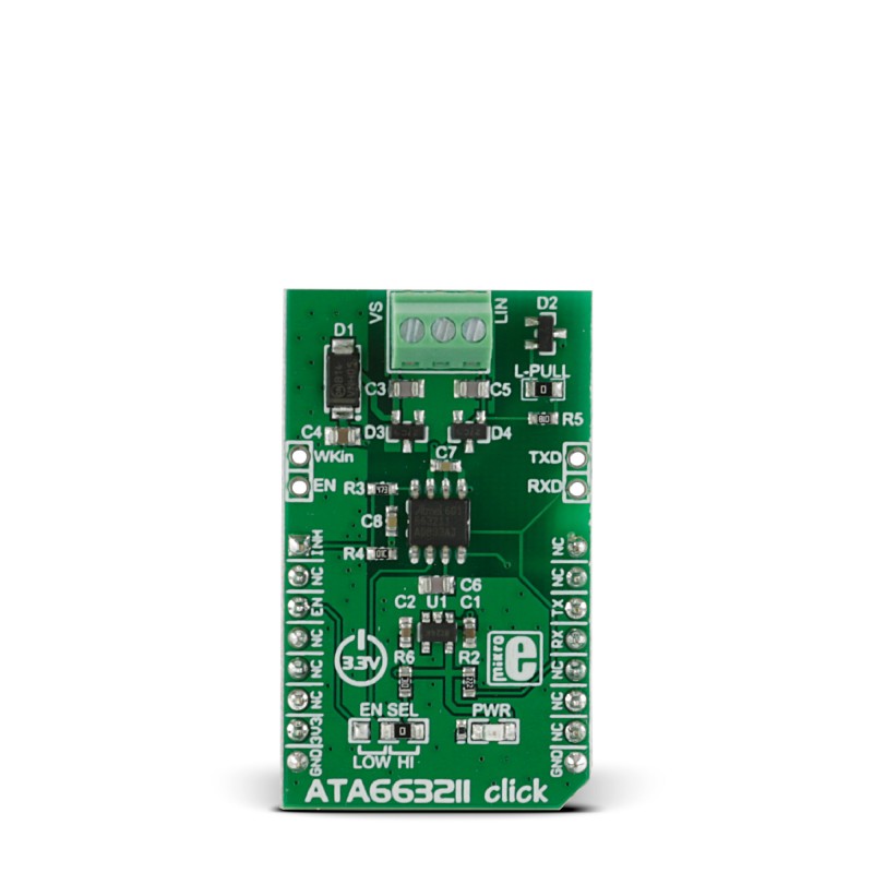
ATA663211 click is a LIN transceiver that carries an Atmel ATA663211 IC and runs on 3.3V power supply. The click communicates with the target MCU through UART connection. The IC is designed to handle low-speed data communication in vehicles.

No Abuse Reported

Do you want to subscribe in order to receive notifications regarding "ATA663211 click" changes.

Do you want to unsubscribe in order to stop receiving notifications regarding "ATA663211 click" changes.

Do you want to report abuse regarding "ATA663211 click".

  • mikroSDK Library 2.0.0.0
  • Comments (0)
DOWNLOAD LINK RELATED COMPILER CONTAINS
mikroBasic PRO for ARM
  • lib
  • src
  • exa
  • hlp
  • hex
  • sch
  • pcb
  • doc
mikroBasic PRO for AVR
  • lib
  • src
  • exa
  • hlp
  • hex
  • sch
  • pcb
  • doc
mikroBasic PRO for dsPIC30/33 & PIC24
  • lib
  • src
  • exa
  • hlp
  • hex
  • sch
  • pcb
  • doc
mikroBasic PRO for FT90x
  • lib
  • src
  • exa
  • hlp
  • hex
  • sch
  • pcb
  • doc
mikroBasic PRO for PIC
  • lib
  • src
  • exa
  • hlp
  • hex
  • sch
  • pcb
  • doc
mikroBasic PRO for PIC32
  • lib
  • src
  • exa
  • hlp
  • hex
  • sch
  • pcb
  • doc
mikroC PRO for ARM
  • lib
  • src
  • exa
  • hlp
  • hex
  • sch
  • pcb
  • doc
mikroC PRO for AVR
  • lib
  • src
  • exa
  • hlp
  • hex
  • sch
  • pcb
  • doc
mikroC PRO for dsPIC30/33 & PIC24
  • lib
  • src
  • exa
  • hlp
  • hex
  • sch
  • pcb
  • doc
mikroC PRO for FT90x
  • lib
  • src
  • exa
  • hlp
  • hex
  • sch
  • pcb
  • doc
mikroC PRO for PIC
  • lib
  • src
  • exa
  • hlp
  • hex
  • sch
  • pcb
  • doc
mikroC PRO for PIC32
  • lib
  • src
  • exa
  • hlp
  • hex
  • sch
  • pcb
  • doc
mikroPascal PRO for ARM
  • lib
  • src
  • exa
  • hlp
  • hex
  • sch
  • pcb
  • doc
mikroPascal PRO for AVR
  • lib
  • src
  • exa
  • hlp
  • hex
  • sch
  • pcb
  • doc
mikroPascal PRO for dsPIC30/33 & PIC24
  • lib
  • src
  • exa
  • hlp
  • hex
  • sch
  • pcb
  • doc
mikroPascal PRO for FT90x
  • lib
  • src
  • exa
  • hlp
  • hex
  • sch
  • pcb
  • doc
mikroPascal PRO for PIC
  • lib
  • src
  • exa
  • hlp
  • hex
  • sch
  • pcb
  • doc
mikroPascal PRO for PIC32
  • lib
  • src
  • exa
  • hlp
  • hex
  • sch
  • pcb
  • doc

mikroSDK Library Blog

ATA663211 click

ATA663211 click

Front view of the ATA663211 click board.

View full image
ATA663211 click

ATA663211 click

Front and back view of the ATA663211 click board.

View full image

Library Description

Defines and initializes driver's UART bus. Declares and defines driver's functions for sending and receiving data bytes, also for checking if data byte ready for reading. It also offers wake-up, sleep mode and check Inhibit pin functions. 

Key functions:

  • void ata663211_writeByte(uint8_t input) - Writes sinle byte in rx buffer.
  • uint8_t ata663211_readByte() - Read received byte from rx buffer.
  • uint8_t ata663211_byteReady() - Checks is there a new byte received.

Examples description

The application is composed of three sections:

  • System Initialization - Initializes UART, LOG structures and sets AN pin as input and CS as output.
  • Application Initialization -  Initalizes UART driver and makes an initial log.
  • Application Task - Checks if new data byte have received in rx buffer (ready for reading), and if ready than reads one byte from rx buffer.
void applicationTask() 
{
    char tmp;
    uint8_t rdyFlag;

// RECEIVER - UART polling

    rdyFlag = ata663211_byteReady();
    
    if (1 == rdyFlag)
    {
        tmp = ata663211_readByte();
        mikrobus_logWrite( &tmp, _LOG_BYTE );
    }
    
// TRANSMITER - TX each 2 sec
/*
    for (tmp = 0; tmp < 9; tmp++)
    {
        ata663211_writeByte( MESSAGE_DATA[tmp] );
        mikrobus_logWrite( "MESSAGE SENT", _LOG_LINE );
    }
    Delay_ms(2000);
*/
}       

Other mikroE Libraries used in the example:

  • UART​

Additional notes and informations

Depending on the development board you are using, you may need USB UART clickUSB UART 2 click or RS232 click to connect to your PC, for development systems with no UART to USB interface available on the board. The terminal available in all MikroElektronika compilers, or any other terminal application of your choice, can be used to read the message

ALSO FROM THIS AUTHOR

Current 2 Click

0

Current 2 Click is an accurate current sensing Click board™ suitable for a very accurate measurement of the current through the load.

[Learn More]

Step Down 8 Click

0

Step Down 8 Click is a compact add-on board that converts higher voltages into a lower voltage level. This board features the MAX25232, a mini buck converter from Analog Devices. It is designed to deliver up to 3A with 3.5V to 36V input voltages while using only 3.5μA quiescent current at no load.

[Learn More]

Stepper 13 Click

0

Stepper 13 Click is a bipolar step motor driver. It features an H-bridge bipolar step motor driver, which supports full-, half-, quarter-, or eighth-step modes. Stepper 13 Click also carries a port expander so that the communication can be done with a minimal number of pins, through the mikroBUS™ I2C bus.

[Learn More]