TOP Contributors

  1. MIKROE (2762 codes)
  2. Alcides Ramos (374 codes)
  3. Shawon Shahryiar (307 codes)
  4. jm_palomino (118 codes)
  5. Bugz Bensce (90 codes)
  6. S P (73 codes)
  7. dany (71 codes)
  8. MikroBUS.NET Team (35 codes)
  9. NART SCHINACKOW (34 codes)
  10. Armstrong Subero (27 codes)

Most Downloaded

  1. Timer Calculator (139254 times)
  2. FAT32 Library (71751 times)
  3. Network Ethernet Library (57122 times)
  4. USB Device Library (47430 times)
  5. Network WiFi Library (43082 times)
  6. FT800 Library (42404 times)
  7. GSM click (29835 times)
  8. mikroSDK (28078 times)
  9. PID Library (26885 times)
  10. microSD click (26198 times)
Libstock prefers package manager

Package Manager

We strongly encourage users to use Package manager for sharing their code on Libstock website, because it boosts your efficiency and leaves the end user with no room for error. [more info]

< Back
mikroSDK Library

PWM driver click

Rating:

0

Author: MIKROE

Last Updated: 2019-03-13

Package Version: 1.0.0.1

mikroSDK Library: 1.0.0.0

Category: PWM

Downloaded: 5709 times

Not followed.

License: MIT license  

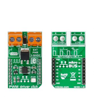
If you need to control DC motors with loads up to 10A, PWM driver click is the perfect solution, thanks to the Silicon Lab Si8711CC one-channel isolator. It communicates with the target MCU over PWM pin, and runs on a 5V power supply.

No Abuse Reported

Do you want to subscribe in order to receive notifications regarding "PWM driver click" changes.

Do you want to unsubscribe in order to stop receiving notifications regarding "PWM driver click" changes.

Do you want to report abuse regarding "PWM driver click".
  • mikroSDK Library 2.0.0.0
  • Comments (0)
DOWNLOAD LINK RELATED COMPILER CONTAINS
mikroBasic PRO for ARM
  • lib
  • src
  • exa
  • hlp
  • hex
  • sch
  • pcb
  • doc
mikroBasic PRO for AVR
  • lib
  • src
  • exa
  • hlp
  • hex
  • sch
  • pcb
  • doc
mikroBasic PRO for dsPIC30/33 & PIC24
  • lib
  • src
  • exa
  • hlp
  • hex
  • sch
  • pcb
  • doc
mikroBasic PRO for FT90x
  • lib
  • src
  • exa
  • hlp
  • hex
  • sch
  • pcb
  • doc
mikroBasic PRO for PIC
  • lib
  • src
  • exa
  • hlp
  • hex
  • sch
  • pcb
  • doc
mikroBasic PRO for PIC32
  • lib
  • src
  • exa
  • hlp
  • hex
  • sch
  • pcb
  • doc
mikroC PRO for ARM
  • lib
  • src
  • exa
  • hlp
  • hex
  • sch
  • pcb
  • doc
mikroC PRO for AVR
  • lib
  • src
  • exa
  • hlp
  • hex
  • sch
  • pcb
  • doc
mikroC PRO for dsPIC30/33 & PIC24
  • lib
  • src
  • exa
  • hlp
  • hex
  • sch
  • pcb
  • doc
mikroC PRO for FT90x
  • lib
  • src
  • exa
  • hlp
  • hex
  • sch
  • pcb
  • doc
mikroC PRO for PIC
  • lib
  • src
  • exa
  • hlp
  • hex
  • sch
  • pcb
  • doc
mikroC PRO for PIC32
  • lib
  • src
  • exa
  • hlp
  • hex
  • sch
  • pcb
  • doc
mikroPascal PRO for ARM
  • lib
  • src
  • exa
  • hlp
  • hex
  • sch
  • pcb
  • doc
mikroPascal PRO for AVR
  • lib
  • src
  • exa
  • hlp
  • hex
  • sch
  • pcb
  • doc
mikroPascal PRO for dsPIC30/33 & PIC24
  • lib
  • src
  • exa
  • hlp
  • hex
  • sch
  • pcb
  • doc
mikroPascal PRO for FT90x
  • lib
  • src
  • exa
  • hlp
  • hex
  • sch
  • pcb
  • doc
mikroPascal PRO for PIC
  • lib
  • src
  • exa
  • hlp
  • hex
  • sch
  • pcb
  • doc
mikroPascal PRO for PIC32
  • lib
  • src
  • exa
  • hlp
  • hex
  • sch
  • pcb
  • doc

mikroSDK Library Blog

PWM driver click

PWM driver click

Front and back view of the PWM driver click board.

View full image

Library Description

The library covers all the necessary functions to control the PWM driver Click board. PWM driver Click communicates with the target board via the PWM module. This library contains drivers for PWM function: initialization, for sets duty ratio, starts and stops PWM module.

Key functions:

  • void pwmdriver_gpioDriverInit( (T_PWMDRIVER_P)&_MIKROBUS1_GPIO ) - Function initializes GPIO driver for the desired MIKROBUS1.

Examples description

The application is composed of three sections:

  • System Initialization - Initializes GPIO and LOG structures, sets AN and INT pins as input and sets RST and PWM pins as output.
  • Application Initialization -  Initialization driver enables - GPIO, PWM initialization set PWM duty cycle and PWM frequency, start PWM, enable the engine, and start to write log.
  • Application Task - (code snippet) This is an example which demonstrates the use of PWM driver Click board. PWM driver Click communicates with register via PWM interface. This example shows the automatic control halogen bulb light intensity, the first intensity of light is rising and then the intensity of light is falling. Results are being sent to the Usart Terminal where you can track their changes.
void applicationTask() 
{
    mikrobus_logWrite( " Light Intensity Rising  ", _LOG_LINE );
    Delay_1sec();
 
    for ( dutyCycle = 5; dutyCycle < 255; dutyCycle += 25 )
    {
        pwmdriver_pwmSetDuty( dutyCycle );
        mikrobus_logWrite( " >", _LOG_TEXT );
        Delay_1sec();
    }
 
    mikrobus_logWrite( "", _LOG_LINE );
    mikrobus_logWrite( "-------------------------", _LOG_LINE );
    mikrobus_logWrite( " Light Intensity Falling ", _LOG_LINE );
    Delay_1sec();
 
    for ( dutyCycle = 255; dutyCycle > 5; dutyCycle -= 25 )
    {
        pwmdriver_pwmSetDuty( dutyCycle );
        mikrobus_logWrite( " <", _LOG_TEXT );
        Delay_1sec();
    }
  
    mikrobus_logWrite( "", _LOG_LINE );
    mikrobus_logWrite( "-------------------------", _LOG_LINE );
    Delay_1sec();
}  

Additional Functions :

  • uint32_t pwmdriver_pwmInit( uint16_t freq ) - Initializes the Timer module in PWM mode.
  • void pwmdriver_pwmSetDuty( uint16_t duty ) - The function changes PWM duty ratio.
  • void pwmdriver_pwmStart() Starts appropriate PWM module.
  • void pwmdriver_pwmStop() - Stops appropriate PWM module.

Other mikroE Libraries used in the example:

  • PWM
  • UART

Additional notes and informations

Depending on the development board you are using, you may need USB UART clickUSB UART 2 click or RS232 click to connect to your PC, for development systems with no UART to USB interface available on the board. The terminal available in all MikroElektronika compilers, or any other terminal application of your choice, can be used to read the message

ALSO FROM THIS AUTHOR

DAC click

0

This example demonstrates usage of the DAC click board in mikroBUS form factor. Board features 12-bit Digital-to-Analog Converter MCP4921 that features SPI interface and an optional double buffered output.

[Learn More]

Brushless 17 Click

0

Brushless 17 Click is a compact add-on board suitable for controlling brushless DC (BLDC) motors with any MCU. This board features the L6229Q, DMOS fully integrated three-phase BLDC motor driver with overcurrent protection from STMicroelectronics. This motor driver combines isolated DMOS power transistors with CMOS and bipolar circuits on the same chip, realized in BCD (Bipolar-CMOS-DMOS) multipower technology. It includes all the circuitry for a three-phase BLDC motor drive, including a three-phase DMOS bridge, a constant off-time PWM current controller, and the decoding logic for single-ended hall sensors that generate the required sequence for the power stage.

[Learn More]

Relay 4 Click

0

Relay 4 Click is a compact add-on board with a general-purpose relay that any host MCU can control. This board features the J1031C3VDC, high-current single-pole double-throw (SPDT) signal relay from CIT Relay and Switch. Highly sensitive, the J1031C3VDC offers a low coil power consumption in a small, lightweight package with PC pin mounting. It comes with a dimension of 12.5x7.5x10 millimetre (LxWxH) and a 1C contact arrangement with a coil voltage of 3VDC, providing a switching voltage of 125VAC/60VDC maximum.

[Learn More]