TOP Contributors

  1. MIKROE (2784 codes)
  2. Alcides Ramos (405 codes)
  3. Shawon Shahryiar (307 codes)
  4. jm_palomino (133 codes)
  5. Bugz Bensce (97 codes)
  6. S P (73 codes)
  7. dany (71 codes)
  8. MikroBUS.NET Team (35 codes)
  9. NART SCHINACKOW (34 codes)
  10. Armstrong Subero (27 codes)

Most Downloaded

  1. Timer Calculator (141237 times)
  2. FAT32 Library (74038 times)
  3. Network Ethernet Library (58662 times)
  4. USB Device Library (48767 times)
  5. Network WiFi Library (44489 times)
  6. FT800 Library (44034 times)
  7. GSM click (30784 times)
  8. mikroSDK (29606 times)
  9. PID Library (27342 times)
  10. microSD click (27223 times)
Libstock prefers package manager

Package Manager

We strongly encourage users to use Package manager for sharing their code on Libstock website, because it boosts your efficiency and leaves the end user with no room for error. [more info]

< Back
mikroSDK Library

MCP73213 click

Rating:

7

Author: MIKROE

Last Updated: 2019-04-03

Package Version: 1.0.0.1

mikroSDK Library: 1.0.0.0

Category: Battery Charger

Downloaded: 4987 times

Not followed.

License: MIT license  

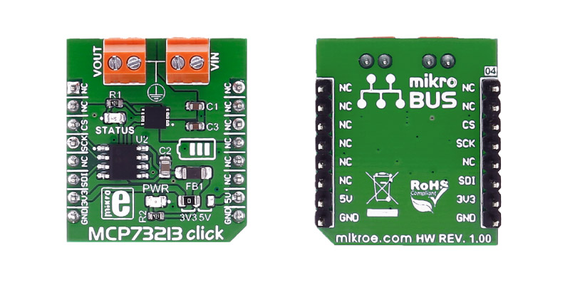
MCP73213 click carries the MCP73213 dual-cell Li-Ion/Li-Polymer battery charge management controller with Input overvoltage protection from Microchip. The click is designed to run on either 3.3V or 5V power supply. It communicates with the target microcontroller over SPI.

No Abuse Reported

Do you want to subscribe in order to receive notifications regarding "MCP73213 click" changes.

Do you want to unsubscribe in order to stop receiving notifications regarding "MCP73213 click" changes.

Do you want to report abuse regarding "MCP73213 click".

  • mikroSDK Library 2.0.0.0
  • Comments (0)
DOWNLOAD LINK RELATED COMPILER CONTAINS
mikroBasic PRO for ARM
  • lib
  • src
  • exa
  • hlp
  • hex
  • sch
  • pcb
  • doc
mikroBasic PRO for AVR
  • lib
  • src
  • exa
  • hlp
  • hex
  • sch
  • pcb
  • doc
mikroBasic PRO for dsPIC30/33 & PIC24
  • lib
  • src
  • exa
  • hlp
  • hex
  • sch
  • pcb
  • doc
mikroBasic PRO for FT90x
  • lib
  • src
  • exa
  • hlp
  • hex
  • sch
  • pcb
  • doc
mikroBasic PRO for PIC
  • lib
  • src
  • exa
  • hlp
  • hex
  • sch
  • pcb
  • doc
mikroBasic PRO for PIC32
  • lib
  • src
  • exa
  • hlp
  • hex
  • sch
  • pcb
  • doc
mikroC PRO for ARM
  • lib
  • src
  • exa
  • hlp
  • hex
  • sch
  • pcb
  • doc
mikroC PRO for AVR
  • lib
  • src
  • exa
  • hlp
  • hex
  • sch
  • pcb
  • doc
mikroC PRO for dsPIC30/33 & PIC24
  • lib
  • src
  • exa
  • hlp
  • hex
  • sch
  • pcb
  • doc
mikroC PRO for FT90x
  • lib
  • src
  • exa
  • hlp
  • hex
  • sch
  • pcb
  • doc
mikroC PRO for PIC
  • lib
  • src
  • exa
  • hlp
  • hex
  • sch
  • pcb
  • doc
mikroC PRO for PIC32
  • lib
  • src
  • exa
  • hlp
  • hex
  • sch
  • pcb
  • doc
mikroPascal PRO for ARM
  • lib
  • src
  • exa
  • hlp
  • hex
  • sch
  • pcb
  • doc
mikroPascal PRO for AVR
  • lib
  • src
  • exa
  • hlp
  • hex
  • sch
  • pcb
  • doc
mikroPascal PRO for dsPIC30/33 & PIC24
  • lib
  • src
  • exa
  • hlp
  • hex
  • sch
  • pcb
  • doc
mikroPascal PRO for FT90x
  • lib
  • src
  • exa
  • hlp
  • hex
  • sch
  • pcb
  • doc
mikroPascal PRO for PIC
  • lib
  • src
  • exa
  • hlp
  • hex
  • sch
  • pcb
  • doc
mikroPascal PRO for PIC32
  • lib
  • src
  • exa
  • hlp
  • hex
  • sch
  • pcb
  • doc

mikroSDK Library Blog

MCP73213 click

MCP73213 click

Front and back view of the MCP73213 click board.

View full image

Library Description

The library covers all the necessary functions to control the MCP73213 click board. MCP73213 click communicates with the device via SPI driver by the write to the registers.

Key functions:

  • void smcp73213_writeData( uint8_t command, uint8_t writeData ) - Generic write the byte of data function.
  • void mcp73213_setCurrentOutput( uint8_t outData ) - Set values for output current function.

Examples description

The application is composed of three sections:

  • System Initialization - Initializes GPIO, SPI, and LOG structures set CS pin as output and start to write log.
  • Application Initialization -  Initialization driver enable's - SPI, also write log.
  • Application Task - (code snippet) This is an example which demonstrates the use of MCP73213 Click board. This example sets the resistance to a given value, thus affecting the output current. Controls output current using an internal digital potentiometer. Results are being sent to the Usart Terminal where you can track their changes. All data logs write on usb uart changes for every 5 sec.
void applicationTask() 
{
    mikrobus_logWrite( "----------------------", _LOG_LINE );
    mikrobus_logWrite( "   10 kOhm - 130 mA   ", _LOG_LINE );
    mcp73213_setCurrentOutput( _MCP73213_OUTPUT_130_mA );
    Delay_ms( 5000 );
    
    mikrobus_logWrite( "----------------------", _LOG_LINE );
    mikrobus_logWrite( "    5 kOhm - 250 mA   ", _LOG_LINE );
    mcp73213_setCurrentOutput( _MCP73213_OUTPUT_250_mA );
    Delay_ms( 5000 );

    mikrobus_logWrite( "----------------------", _LOG_LINE );
    mikrobus_logWrite( "  2,1 kOhm - 550 mA   ", _LOG_LINE );
    mcp73213_setCurrentOutput( _MCP73213_OUTPUT_550_mA );
    Delay_ms( 5000 );

    mikrobus_logWrite( "----------------------", _LOG_LINE );
    mikrobus_logWrite( "   1 kOhm - 1100 mA   ", _LOG_LINE );
    mcp73213_setCurrentOutput( _MCP73213_OUTPUT_1100_mA );
    Delay_ms( 5000 );
}        

Other mikroE Libraries used in the example:

  • SPI
  • UART​

Additional notes and informations

Depending on the development board you are using, you may need USB UART clickUSB UART 2 click or RS232 click to connect to your PC, for development systems with no UART to USB interface available on the board. The terminal available in all MikroElektronika compilers, or any other terminal application of your choice, can be used to read the message

ALSO FROM THIS AUTHOR

PROFET 2 3A Click

0

PROFET 2 Click is a compact add-on board that contains a smart high-side power switch. This board features the BTS70802EPAXUMA1, a dual-channel, high-side power switch with embedded protection and diagnosis feature from Infineon Technologies.

[Learn More]

ccRF 2 click

1

This is a sample program which demonstrates the use of ccRF2 click. Programmer uses RF module for communication between two development systems. Each module can be used as transmitter and receiver.

[Learn More]

Multi Stepper TB67S101 Click

0

Multi Stepper Click is a compact add-on board that contains a bipolar stepper motor driver. This board features the TB67S101AFG, a PHASE-in controlled bipolar stepping motor driver from Toshiba Semiconductor. It supports a PWM constant-current control drive and full-, half-, and quarter-step operation for less motor noise and smoother control. It has a wide operating voltage range of 10V to 47V with an output current capacity of 2.8A in addition to several built-in error detection circuits.

[Learn More]