We strongly encourage users to use Package manager for sharing their code on Libstock website, because it boosts your efficiency and leaves the end user with no room for error. [more info]

Rating:
Author: MIKROE
Last Updated: 2019-07-29
Package Version: 1.0.0.1
mikroSDK Library: 1.0.0.0
Category: ADC-DAC
Downloaded: 6164 times
Not followed.
License: MIT license
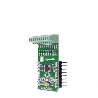
ADAC click is an 8-channel 12bit ADC, DAC and GPIO converter. The click is designed to run on either 3.3V or 5V power supply. ADAC click communicates with the target microcontroller over I2C interface, with additional functionality provided by the RST pin on the mikroBUSâ„¢ line.
Do you want to subscribe in order to receive notifications regarding "ADAC click" changes.
Do you want to unsubscribe in order to stop receiving notifications regarding "ADAC click" changes.
Do you want to report abuse regarding "ADAC click".

Library Description
The library covers all the necessary functions that enables the usage of the ADAC click board.
It initializes and defines the I2C driver and drivers that offer a choice for reading and writing DAC
data from and to all eight channels and reading ADC data from all eight channels. User also has diferent
functions that allow diferent settings at his disposal.
Key functions:
void adac_setConfiguration( uint8_t ptByte, uint8_t msbData, uint8_t lsbData ) - Function is used to configure the device to users needs.void adac_writeDACData( uint8_t wrChann, uint16_t wrData ) - Function is used to write 16-bit data to the designated channel.uint16_t adac_readADC( uint8_t *IOChannel ) - Function is used to read ADC value from any of the channels.Examples description
The application is composed of three sections :
void applicationTask()
{
    uint16_t i;
    uint16_t ADCValue;
    uint8_t channel;
    char logTxt[ 50 ];

mikrobus_logWrite( " Write DAC demonstration  ", _LOG_LINE );
    adac_setConfiguration( _ADAC_DAC_CONFIG, _ADAC_NO_OP, _ADAC_IO3 );
    Delay_ms( 100 );
    for ( i = 0; i < 0XFF; i += 4 )
    {
        adac_writeDAC( _ADAC_PB_PIN3, i / 0x100, i % 0x100 );
        Delay_ms( 10 );
        mikrobus_logWrite( " * ", _LOG_LINE );

            }
    mikrobus_logWrite( " Demonstration finished  ", _LOG_LINE );
    mikrobus_logWrite( "-------------------------", _LOG_LINE );
    Delay_ms( 1000 );
        mikrobus_logWrite( " Read ADC demonstration  ", _LOG_LINE );
    adac_setConfiguration( _ADAC_ADC_CONFIG, _ADAC_NO_OP, _ADAC_IO4 );
    Delay_ms( 100 );
    adac_setConfiguration( _ADAC_ADC_SEQUENCE, _ADAC_SEQUENCE_ON, _ADAC_IO4 );
    for ( i = 0; i < 10; i++ )
    {
        ADCValue = adac_readADC( &channel );
        ShortToStr( channel, logTxt );
        Ltrim( logTxt );
        mikrobus_logWrite( "ADC value on channel ", _LOG_TEXT );
        mikrobus_logWrite( logTxt, _LOG_TEXT );
        mikrobus_logWrite( " is : ", _LOG_TEXT );
        WordToStr( ADCValue, logTxt );
        Ltrim( logTxt );
        mikrobus_logWrite( logTxt, _LOG_LINE );
        Delay_ms( 2000 );
    }
    mikrobus_logWrite( " Demonstration finished  ", _LOG_LINE );
    mikrobus_logWrite( "-------------------------", _LOG_LINE );
    Delay_ms( 1000 );
}
Other mikroE Libraries used in the example:
Additional notes and informations
Depending on the development board you are using, you may need USB UART click, USB UART 2 click or RS232 click to connect to your PC, for development systems with no UART to USB interface available on the board. The terminal available in all MikroElektronika compilers, or any other terminal application of your choice, can be used to read the message.