TOP Contributors

  1. MIKROE (2779 codes)
  2. Alcides Ramos (376 codes)
  3. Shawon Shahryiar (307 codes)
  4. jm_palomino (118 codes)
  5. Bugz Bensce (97 codes)
  6. S P (73 codes)
  7. dany (71 codes)
  8. MikroBUS.NET Team (35 codes)
  9. NART SCHINACKOW (34 codes)
  10. Armstrong Subero (27 codes)

Most Downloaded

  1. Timer Calculator (139566 times)
  2. FAT32 Library (72041 times)
  3. Network Ethernet Library (57256 times)
  4. USB Device Library (47615 times)
  5. Network WiFi Library (43219 times)
  6. FT800 Library (42566 times)
  7. GSM click (29930 times)
  8. mikroSDK (28292 times)
  9. PID Library (26933 times)
  10. microSD click (26309 times)
Libstock prefers package manager

Package Manager

We strongly encourage users to use Package manager for sharing their code on Libstock website, because it boosts your efficiency and leaves the end user with no room for error. [more info]

< Back
mikroSDK Library

7-SEG RGB click

Rating:

0

Author: MIKROE

Last Updated: 2019-05-23

Package Version: 1.0.0.1

mikroSDK Library: 1.0.0.0

Category: LED segment

Downloaded: 2986 times

Not followed.

License: MIT license  

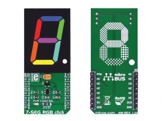
7-SEG RGB click carries a full color single 7 segment digit display. The click is designed to run on either 3.3V or 5V power supply. It communicates with the target microcontroller over the CS, and PWM pin on the mikroBUS line.

No Abuse Reported

Do you want to subscribe in order to receive notifications regarding "7-SEG RGB click" changes.

Do you want to unsubscribe in order to stop receiving notifications regarding "7-SEG RGB click" changes.

Do you want to report abuse regarding "7-SEG RGB click".
  • mikroSDK Library 2.0.0.0
  • Comments (0)

mikroSDK Library Blog

7-SEG RGB

7-SEG RGB

Front and Back view of the 7-SEG RGB board.

View full image

Library Description

The library covers all the necessary functions to control 7-SEG RGB click board.

Key functions:

  • void c7segrgb_gpioDriverInit(T_PS2_P gpioObj) - Function initializes GPIO driver for the desired MIKROBUS1.

Examples description

The application is composed of the three sections :

  • System Initialization - Initializes GPIO, LOG structures.
  • Application Initialization -  Initialization driver enables - GPIO.
  • Application Task - (code snippet) This is an example which demonstrates the use of 7-SEG RGB Click board. This simple example shows all ten numbers in different colors on 7-SEG RGB click.
void applicationTask() 
{
    uint8_t cnt_i;
    uint8_t cnt_j;
    
    for ( cnt_i = 0; cnt_i < 10; cnt_i++ )
    {
        for ( cnt_j = 10; cnt_j > 0; cnt_j-- )
        {
            c7segrgb_setSevenSegment( _CHARACTER_TABLE[ cnt_i ], 4 * cnt_i, 4 * cnt_j, cnt_i * cnt_j );
            Delay_100ms();
        }
    }

    c7segrgb_setSevenSegment( _C7SEGRGB_POINT, 10, 10, 10 );
    Delay_1sec();

    c7segrgb_setSevenSegment( _C7SEGRGB_ZERO, 40, 40, 40 );
    Delay_1sec();

    c7segrgb_setSevenSegment( _C7SEGRGB_ONE, 40, 0, 0 );
    Delay_1sec();

    c7segrgb_setSevenSegment( _C7SEGRGB_TWO, 0, 40, 0 );
    Delay_1sec();

    c7segrgb_setSevenSegment( _C7SEGRGB_THREE, 0, 0, 40 );
    Delay_1sec();

    c7segrgb_setSevenSegment( _C7SEGRGB_FOUR, 40, 0, 40 );
    Delay_1sec();

    c7segrgb_setSevenSegment( _C7SEGRGB_FIVE, 0, 40, 40 );
    Delay_1sec();

    c7segrgb_setSevenSegment( _C7SEGRGB_SIX, 40, 40, 0 );
    Delay_1sec();

    c7segrgb_setSevenSegment( _C7SEGRGB_SEVEN, 20, 30, 40 );
    Delay_1sec();

    c7segrgb_setSevenSegment( _C7SEGRGB_EIGHT, 40, 15, 31 );
    Delay_1sec();

    c7segrgb_setSevenSegment( _C7SEGRGB_NINE, 20, 10, 30 );
    Delay_1sec();

    RGB_CONTROL_BIT = 0;
}        

Additional Functions :

  • void c7segrgb_logicOne() - Generic logic one function.
  • void c7segrgb_logicZero() - Generic logic zero function.
  • void c7segrgb_setColor( uint8_t _green, uint8_t _red, uint8_t _blue ) - Set the color of the  LSB segment of the display function.
  • void c7segrgb_setSevenSegment( uint8_t  _character, uint8_t _greenBrightness, uint8_t _redBrightness, uint8_t _blueBrightness ) - Set whole character and color function.

Other mikroE Libraries used in the example:

  • One_Wire
  • UART​
  • Conversion

Additional notes and informations

Depending on the development board you are using, you may need USB UART clickUSB UART 2 click or RS232 click to connect to your PC, for development systems with no UART to USB interface available on the board. The terminal available in all MikroElektronika compilers, or any other terminal application of your choice, can be used to read the message

ALSO FROM THIS AUTHOR

ADC click

0

Simple example which demonstrates working with the 4-Channel 12-bit A/D Converter (MCP3204) with SPI Serial Interface. The example shows how to measure analog inputs on Channels 0, 1, 2 and 3 and display the results on LCD.

[Learn More]

Temp-Log 3 click

5

Temp-Log 3 click is a temperature measuring Click board featuring the MCP9843 IC, an accurate temperature sensor IC with integrated EEPROM.

[Learn More]

Semper Flash Click

0

The Semper Flash Click is a Click board™ which features the S25HS512T, a perfect solution for the mass storage option in various embedded applications. With fast performance being one of its key features, Semper Flash Click can also be used for the code shadowing, execute-in-place (XIP), data logging and data storage.

[Learn More]