TOP Contributors

  1. MIKROE (2784 codes)
  2. Alcides Ramos (388 codes)
  3. Shawon Shahryiar (307 codes)
  4. jm_palomino (120 codes)
  5. Bugz Bensce (97 codes)
  6. S P (73 codes)
  7. dany (71 codes)
  8. MikroBUS.NET Team (35 codes)
  9. NART SCHINACKOW (34 codes)
  10. Armstrong Subero (27 codes)

Most Downloaded

  1. Timer Calculator (140180 times)
  2. FAT32 Library (72630 times)
  3. Network Ethernet Library (57648 times)
  4. USB Device Library (47959 times)
  5. Network WiFi Library (43556 times)
  6. FT800 Library (42955 times)
  7. GSM click (30142 times)
  8. mikroSDK (28681 times)
  9. PID Library (27058 times)
  10. microSD click (26553 times)
Libstock prefers package manager

Package Manager

We strongly encourage users to use Package manager for sharing their code on Libstock website, because it boosts your efficiency and leaves the end user with no room for error. [more info]

< Back
mikroSDK Library

LED Driver 2 click

Rating:

0

Author: MIKROE

Last Updated: 2019-03-15

Package Version: 1.0.0.1

mikroSDK Library: 1.0.0.0

Category: LED Drivers

Downloaded: 4285 times

Not followed.

License: MIT license  

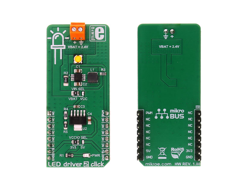
LED driver 2 click carries the MCP1643 - LED constant current regulator, made by Microchip. It is a compact, high-efficiency, fixed frequency, synchronous step-up converter, optimized to drive one LED with the constant current. It can be powered by a two-cell alkaline/NiMH/NiCd battery (2.4V), or via the mikroBUSâ„¢ power supply pins.

No Abuse Reported
  • mikroSDK Library 2.0.0.0
  • Comments (0)
DOWNLOAD LINK RELATED COMPILER CONTAINS
mikroBasic PRO for ARM
  • lib
  • src
  • exa
  • hlp
  • hex
  • sch
  • pcb
  • doc
mikroBasic PRO for AVR
  • lib
  • src
  • exa
  • hlp
  • hex
  • sch
  • pcb
  • doc
mikroBasic PRO for dsPIC30/33 & PIC24
  • lib
  • src
  • exa
  • hlp
  • hex
  • sch
  • pcb
  • doc
mikroBasic PRO for FT90x
  • lib
  • src
  • exa
  • hlp
  • hex
  • sch
  • pcb
  • doc
mikroBasic PRO for PIC
  • lib
  • src
  • exa
  • hlp
  • hex
  • sch
  • pcb
  • doc
mikroBasic PRO for PIC32
  • lib
  • src
  • exa
  • hlp
  • hex
  • sch
  • pcb
  • doc
mikroC PRO for ARM
  • lib
  • src
  • exa
  • hlp
  • hex
  • sch
  • pcb
  • doc
mikroC PRO for AVR
  • lib
  • src
  • exa
  • hlp
  • hex
  • sch
  • pcb
  • doc
mikroC PRO for dsPIC30/33 & PIC24
  • lib
  • src
  • exa
  • hlp
  • hex
  • sch
  • pcb
  • doc
mikroC PRO for FT90x
  • lib
  • src
  • exa
  • hlp
  • hex
  • sch
  • pcb
  • doc
mikroC PRO for PIC
  • lib
  • src
  • exa
  • hlp
  • hex
  • sch
  • pcb
  • doc
mikroC PRO for PIC32
  • lib
  • src
  • exa
  • hlp
  • hex
  • sch
  • pcb
  • doc
mikroPascal PRO for ARM
  • lib
  • src
  • exa
  • hlp
  • hex
  • sch
  • pcb
  • doc
mikroPascal PRO for AVR
  • lib
  • src
  • exa
  • hlp
  • hex
  • sch
  • pcb
  • doc
mikroPascal PRO for dsPIC30/33 & PIC24
  • lib
  • src
  • exa
  • hlp
  • hex
  • sch
  • pcb
  • doc
mikroPascal PRO for FT90x
  • lib
  • src
  • exa
  • hlp
  • hex
  • sch
  • pcb
  • doc
mikroPascal PRO for PIC
  • lib
  • src
  • exa
  • hlp
  • hex
  • sch
  • pcb
  • doc
mikroPascal PRO for PIC32
  • lib
  • src
  • exa
  • hlp
  • hex
  • sch
  • pcb
  • doc

mikroSDK Library Blog

LED Driver 2 click

LED Driver 2 click

Front and back view of the LED Driver 2 click board.

View full image

Library Description

The library covers all the necessary functions to control LED Driver 2 click board. LED Driver 2 click communicates with the target board via PWM module. This library contains drivers for PWM function: 
initialization, for sets duty ratio, starts and stops PWM module.

Key functions:

  • leddriver2_gpioDriverInit( (T_LEDDRIVER_P)&_MIKROBUS1_GPIO ) - Function initializes GPIO driver for the desired MIKROBUS1.

Examples description

The application is composed of three sections:

  • System Initialization - Initializes GPIO and LOG structures, PWM pins as output and starts to write log.
  • Application Initialization -  Initialization driver enables - GPIO, PWM initialization set PWM duty cycle and PWM frequency and start PWM.
  • Application Task - (code snippet) This is an example which demonstrates the use of LED Driver 2 click board. LED Driver 2 click communicates with register via PWM interface. This example shows the automatic control halogen bulb light intensity, the first intensity of light is rising and then the intensity of light is falling. Results are being sent to the Usart Terminal where you can track their changes.
void applicationTask() 
{
    mikrobus_logWrite( " Light Intensity Rising  ", _LOG_LINE );
    Delay_1sec();
 
    for ( dutyCycle = 5; dutyCycle < 255; dutyCycle += 25 )
    {
        leddriver2_pwmSetDuty( dutyCycle );
        mikrobus_logWrite( " >", _LOG_TEXT );
        Delay_100ms();
    }
 
    mikrobus_logWrite( ">", _LOG_LINE );
    mikrobus_logWrite( "-------------------------", _LOG_LINE );
    mikrobus_logWrite( " Light Intensity Falling ", _LOG_LINE );
    Delay_1sec();
 
    for ( dutyCycle = 255; dutyCycle > 5; dutyCycle -= 25 )
    {
        leddriver2_pwmSetDuty( dutyCycle );
        mikrobus_logWrite( " <", _LOG_TEXT );
        Delay_100ms();
    }
  
    mikrobus_logWrite( "<", _LOG_LINE );
    mikrobus_logWrite( "-------------------------", _LOG_LINE );
    Delay_1sec();
}  

Additional Functions :

  • uint32_t leddriver2_pwmInit( uint16_t freq ) - Initializes the Timer module in PWM mode.
  • void leddriver2_pwmSetDuty( uint16_t duty ) - The function changes PWM duty ratio.
  • void leddriver2_pwmStart() Starts appropriate PWM module.
  • void leddriver2_pwmStop() - Stops appropriate PWM module.

Other mikroE Libraries used in the example:

  • PWM
  • UART

Additional notes and informations

Depending on the development board you are using, you may need USB UART clickUSB UART 2 click or RS232 click to connect to your PC, for development systems with no UART to USB interface available on the board. The terminal available in all MikroElektronika compilers, or any other terminal application of your choice, can be used to read the message

ALSO FROM THIS AUTHOR

SQI FLASH Click

0

SQI FLASH Click is based on the SST26VF064B, a 64 Mbit Serial Quad I/O flash device from Microchip. The chip utilizes 4-bit multiplexed I/O serial interface to boost the performance. The Click is a very fast solid-state, non-volatile data storage medium, that can be electrically erased and reprogrammed.

[Learn More]

ADC 10 Click

0

ADC 10 Click is a compact add-on board that contains a high-performance data converter. This board features the ADS122U04, a 24-bit precision ΔΣ analog-to-digital converter with UART compatible interface from Texas Instruments.

[Learn More]

Joystick 3 Click

0

Joystick 3 Click is a compact add-on board that can fulfill your directional analog input needs. This board features 2765, a high-quality mini 2-axis analog output thumbstick from Adafruit Industries. This small joystick is a 'self-centering' analog-type with a black rocker cap similar to the PSP joysticks. It comprises two 10kΩ potentiometers, one for up/down and another for left/right direction. Knowing that this joystick represents an analog type, it connects with mikroBUS™ through the SPI interface through the MCP3204 12-bit A/D converter.

[Learn More]
Close menu