TOP Contributors

  1. MIKROE (2784 codes)
  2. Alcides Ramos (405 codes)
  3. Shawon Shahryiar (307 codes)
  4. jm_palomino (133 codes)
  5. Bugz Bensce (97 codes)
  6. S P (73 codes)
  7. dany (71 codes)
  8. MikroBUS.NET Team (35 codes)
  9. NART SCHINACKOW (34 codes)
  10. Armstrong Subero (27 codes)

Most Downloaded

  1. Timer Calculator (142033 times)
  2. FAT32 Library (75258 times)
  3. Network Ethernet Library (59478 times)
  4. USB Device Library (49497 times)
  5. Network WiFi Library (45271 times)
  6. FT800 Library (44889 times)
  7. GSM click (31421 times)
  8. mikroSDK (30421 times)
  9. microSD click (27781 times)
  10. PID Library (27616 times)
Libstock prefers package manager

Package Manager

We strongly encourage users to use Package manager for sharing their code on Libstock website, because it boosts your efficiency and leaves the end user with no room for error. [more info]

< Back
mikroSDK Library

Boost 2 click

Rating:

5

Author: MIKROE

Last Updated: 2018-03-13

Package Version: 1.0.0.0

mikroSDK Library: 1.0.0.0

Category: Boost

Downloaded: 5986 times

Not followed.

License: MIT license  

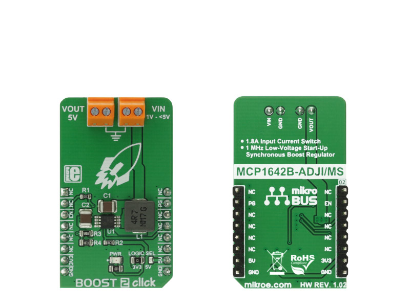
Boost 2 click is a DC-DC step-up (boost) regulator that has a fixed 5V output, which can be obtained from any low voltage input - such as NiCd, NiMH or one cell Li-Po/Li-Ion batteries.

No Abuse Reported

Do you want to subscribe in order to receive notifications regarding "Boost 2 click" changes.

Do you want to unsubscribe in order to stop receiving notifications regarding "Boost 2 click" changes.

Do you want to report abuse regarding "Boost 2 click".

  • mikroSDK Library 2.0.0.0
  • Comments (0)
DOWNLOAD LINK RELATED COMPILER CONTAINS
mikroBasic PRO for ARM
  • lib
  • src
  • exa
  • hlp
  • hex
  • sch
  • pcb
  • doc
mikroBasic PRO for AVR
  • lib
  • src
  • exa
  • hlp
  • hex
  • sch
  • pcb
  • doc
mikroBasic PRO for dsPIC30/33 & PIC24
  • lib
  • src
  • exa
  • hlp
  • hex
  • sch
  • pcb
  • doc
mikroBasic PRO for FT90x
  • lib
  • src
  • exa
  • hlp
  • hex
  • sch
  • pcb
  • doc
mikroBasic PRO for PIC
  • lib
  • src
  • exa
  • hlp
  • hex
  • sch
  • pcb
  • doc
mikroBasic PRO for PIC32
  • lib
  • src
  • exa
  • hlp
  • hex
  • sch
  • pcb
  • doc
mikroC PRO for ARM
  • lib
  • src
  • exa
  • hlp
  • hex
  • sch
  • pcb
  • doc
mikroC PRO for AVR
  • lib
  • src
  • exa
  • hlp
  • hex
  • sch
  • pcb
  • doc
mikroC PRO for dsPIC30/33 & PIC24
  • lib
  • src
  • exa
  • hlp
  • hex
  • sch
  • pcb
  • doc
mikroC PRO for FT90x
  • lib
  • src
  • exa
  • hlp
  • hex
  • sch
  • pcb
  • doc
mikroC PRO for PIC
  • lib
  • src
  • exa
  • hlp
  • hex
  • sch
  • pcb
  • doc
mikroC PRO for PIC32
  • lib
  • src
  • exa
  • hlp
  • hex
  • sch
  • pcb
  • doc
mikroPascal PRO for ARM
  • lib
  • src
  • exa
  • hlp
  • hex
  • sch
  • pcb
  • doc
mikroPascal PRO for AVR
  • lib
  • src
  • exa
  • hlp
  • hex
  • sch
  • pcb
  • doc
mikroPascal PRO for dsPIC30/33 & PIC24
  • lib
  • src
  • exa
  • hlp
  • hex
  • sch
  • pcb
  • doc
mikroPascal PRO for FT90x
  • lib
  • src
  • exa
  • hlp
  • hex
  • sch
  • pcb
  • doc
mikroPascal PRO for PIC
  • lib
  • src
  • exa
  • hlp
  • hex
  • sch
  • pcb
  • doc
mikroPascal PRO for PIC32
  • lib
  • src
  • exa
  • hlp
  • hex
  • sch
  • pcb
  • doc

mikroSDK Library Blog

Boost 2 Click

Boost 2 Click

Native view of the Boost 2 Click board.

View full image
Boost 2 Click

Boost 2 Click

Front and back view of the Boost 2 Click board.

View full image

Library description

This library contains functions that control the Enable pin and can retrieve the state of the PG pin.

Key functions:

void boost2_setENpin(uint8_t newState)- Sets the EN pin

uint8_t boost2_getPGpin()- Gets the status of the PG pin

Example description

The application is composed of three sections :

  • System Initialization - Initializes PIN directions and UART logger
  • Application Initialization - Initializes click driver
  • Application Task (code snippet) - Demonstrates the use of the click drivers function. It shows how to enable or disable click operation, and how to check if supplied voltage is good.
void applicationTask()
{
    mikrobus_logWrite("Enabling click operation...", _LOG_LINE);
    boost2_setENpin(1);
    Delay_ms(3000);

    mikrobus_logWrite("Checking output voltage...", _LOG_LINE);
    Delay_ms(500);
    if(boost2_getPGpin())
    {
        mikrobus_logWrite("Output voltage good.", _LOG_LINE);
    }
    else
    {
        mikrobus_logWrite("Output voltage incorrect.", _LOG_LINE);
    }
    Delay_ms(3000);

    mikrobus_logWrite("Disabling click operation...", _LOG_LINE);
    boost2_setENpin(0);
    Delay_ms(5000);
}


MikroElektronika libraries used in this example:

  • UART

Additional notes and information

Depending on the development board you are using, you may need USB UART clickUSB UART 2 clickor RS232 click to connect to your PC, for development systems with no UART to USB interface available on the board. The terminal available in all MikroElektronika compilers, or any other terminal application of your choice, can be used to read the message.


ALSO FROM THIS AUTHOR

DAC 2 Click

0

DAC 2 Click represents a 16-bit digital-to-analog converter.

[Learn More]

RTC click

0

Example for RTC click board in mikroBUS form factor. It is a simple demonstration how to read/write date and time from PCF8583 RTC (real-time clock). Date and time are read from the RTC every 10 milliseconds and printed on LCD. Communication with the board is done via I2C interface;

[Learn More]

ADC 11 Click

0

ADC 11 Click is a compact add-on board that contains a high-performance data converter. This board features the LTC1864, a 16-bit 250ksps analog-to-digital converter from Analog Devices. With a typical supply current of only 850µA at the maximum sampling frequency, the LTC1864 is among the lowest power consumption ADCs available. After conversion, the LTC1864 goes into a low-power Sleep mode, further reducing the supply current. That’s why it can run at proper micro-power levels in applications that do not require the maximum sampling rate of the LTC1864. This Click board™ is suitable for high-speed data acquisition, low power battery-operated instrumentation, isolated and remote data acquisition, and many other applications.

[Learn More]