TOP Contributors

  1. MIKROE (2784 codes)
  2. Alcides Ramos (405 codes)
  3. Shawon Shahryiar (307 codes)
  4. jm_palomino (133 codes)
  5. Bugz Bensce (97 codes)
  6. S P (73 codes)
  7. dany (71 codes)
  8. MikroBUS.NET Team (35 codes)
  9. NART SCHINACKOW (34 codes)
  10. Armstrong Subero (27 codes)

Most Downloaded

  1. Timer Calculator (141304 times)
  2. FAT32 Library (74107 times)
  3. Network Ethernet Library (58718 times)
  4. USB Device Library (48830 times)
  5. Network WiFi Library (44526 times)
  6. FT800 Library (44078 times)
  7. GSM click (30834 times)
  8. mikroSDK (29673 times)
  9. PID Library (27357 times)
  10. microSD click (27251 times)
Libstock prefers package manager

Package Manager

We strongly encourage users to use Package manager for sharing their code on Libstock website, because it boosts your efficiency and leaves the end user with no room for error. [more info]

< Back
mikroSDK Library

ADC 4 click

Rating:

5

Author: MIKROE

Last Updated: 2018-01-18

Package Version: 1.0.0.0

mikroSDK Library: 1.0.0.0

Category: ADC

Downloaded: 7251 times

Not followed.

License: MIT license  

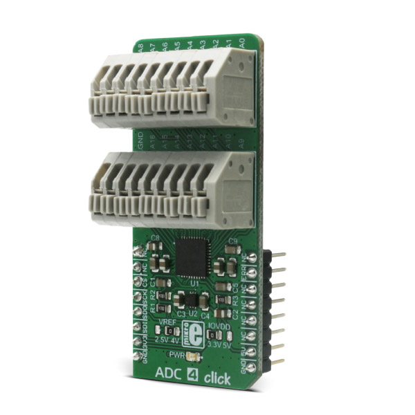
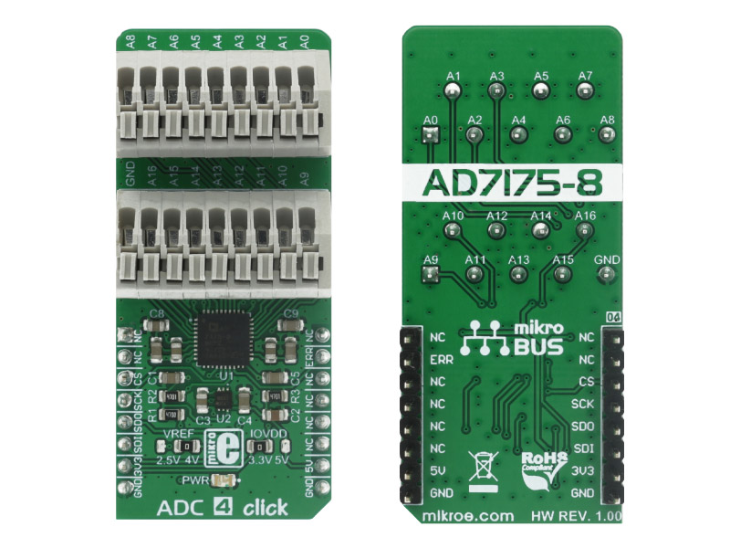
ADC 4 click is an advanced analog to digital multi-channel converter, which can sample inputs from 16 single-ended channels or 8 differential input channel pairs.

No Abuse Reported

Do you want to subscribe in order to receive notifications regarding "ADC 4 click" changes.

Do you want to unsubscribe in order to stop receiving notifications regarding "ADC 4 click" changes.

Do you want to report abuse regarding "ADC 4 click".

  • mikroSDK Library 2.0.0.0
  • Comments (0)
DOWNLOAD LINK RELATED COMPILER CONTAINS
mikroBasic PRO for ARM
  • lib
  • src
  • exa
  • hlp
  • hex
  • sch
  • pcb
  • doc
mikroC PRO for ARM
  • lib
  • src
  • exa
  • hlp
  • hex
  • sch
  • pcb
  • doc
mikroPascal PRO for ARM
  • lib
  • src
  • exa
  • hlp
  • hex
  • sch
  • pcb
  • doc
mikroBasic PRO for AVR
  • lib
  • src
  • exa
  • hlp
  • hex
  • sch
  • pcb
  • doc
mikroC PRO for AVR
  • lib
  • src
  • exa
  • hlp
  • hex
  • sch
  • pcb
  • doc
mikroPascal PRO for AVR
  • lib
  • src
  • exa
  • hlp
  • hex
  • sch
  • pcb
  • doc
mikroBasic PRO for dsPIC30/33 & PIC24
  • lib
  • src
  • exa
  • hlp
  • hex
  • sch
  • pcb
  • doc
mikroC PRO for dsPIC30/33 & PIC24
  • lib
  • src
  • exa
  • hlp
  • hex
  • sch
  • pcb
  • doc
mikroPascal PRO for dsPIC30/33 & PIC24
  • lib
  • src
  • exa
  • hlp
  • hex
  • sch
  • pcb
  • doc
mikroBasic PRO for FT90x
  • lib
  • src
  • exa
  • hlp
  • hex
  • sch
  • pcb
  • doc
mikroC PRO for FT90x
  • lib
  • src
  • exa
  • hlp
  • hex
  • sch
  • pcb
  • doc
mikroPascal PRO for FT90x
  • lib
  • src
  • exa
  • hlp
  • hex
  • sch
  • pcb
  • doc
mikroBasic PRO for PIC
  • lib
  • src
  • exa
  • hlp
  • hex
  • sch
  • pcb
  • doc
mikroC PRO for PIC
  • lib
  • src
  • exa
  • hlp
  • hex
  • sch
  • pcb
  • doc
mikroPascal PRO for PIC
  • lib
  • src
  • exa
  • hlp
  • hex
  • sch
  • pcb
  • doc
mikroBasic PRO for PIC32
  • lib
  • src
  • exa
  • hlp
  • hex
  • sch
  • pcb
  • doc
mikroC PRO for PIC32
  • lib
  • src
  • exa
  • hlp
  • hex
  • sch
  • pcb
  • doc
mikroPascal PRO for PIC32
  • lib
  • src
  • exa
  • hlp
  • hex
  • sch
  • pcb
  • doc

mikroSDK Library Blog

ADC 4 Click

ADC 4 Click

Native view of the ADC 4 Click board.

View full image
ADC 4 Click

ADC 4 Click

Front and back view of the ADC 4 Click board.

View full image

Library Description

Initializes and defines GPIO port driver and driver functions which are realized for communication via SPI bus and for calculating and converting analog signal to a digital one, according to the value of the referent voltage.

Key functions

uint8_t adc4_writeReg( const uint8_t regAddress, uint8_t *value );- This function writes data in the register determined by register address parameter of the function.

uint8_t adc4_readReg( const uint8_t regAddress, uint8_t *value );- This function reads data from the register determined by register address parameter of the function.

void adc4_reset(void);- This function reset ADC 4 click.

uint8_t adc4_getErrPin(void);- This function returns the value of INT (ERROR) pin which is controlled by ERR_DAT bit in the GPIOCON register.

void adc4_getConfig( const uint8_t regAddress, uint16_t *value );- This function writes the value of the configuration registers in storage determined by pointer value.

void adc4_setConfig( const uint8_t regAddress, uint16_t value );- This function writes a 16-bit value in the configuration registers determined by register address parameter.

uint32_t adc4_getData(void);- This function checks ready bit, is data ready or not, and returns 24-bit value from the data register.

uint16_t adc4_getVoltage(void);- This function returns 16-bit calculated value and AD converted voltage value.

Examples Description

The demo application is composed of three sections:

  • System Initialization - Initializes GPIO pins (CS, INT), SPI module for communication with ADC 4 click and UART for data logging.
  • Application Initialization - Initializes ADC 4 driver and sets up working mode.
  • Application Task - (code snippet) - Sequential read of voltage. Information about the current voltage is logged to UART. Operation is repeated each second. Settings are set to calculate and convert input voltage in the range from -2.5V to 2.5V.
void applicationTask()
{
    voltage = adc4_getVoltage();

    IntToStr( voltage, text );
    mikrobus_logWrite( "Current Voltage : ", _LOG_TEXT );
    mikrobus_logWrite( text, _LOG_TEXT );
    mikrobus_logWrite( " mV", _LOG_LINE );

    Delay_ms( 1000 );
}

Other MikroElektronika libraries used in the example:

  • Conversions
  • C_String
  • SPI
  • UART

Additional notes and information

Depending on the development board you are using, you may need USB UART click,  USB UART 2 click or  RS232 click to connect to your PC, for development systems with no UART to USB interface available on the board. The terminal available in all MikroElektronika compilers, or any other terminal application of your choice, can be used to read the message.

ALSO FROM THIS AUTHOR

Matrix R Click

0

Matrix R Click is a mikroBUS add-on board with two red 5x7 matrices driven by two MAX7219 8-bit LED Display Drivers. The active area of each matrix is 7.62mm high and 5.08 mm wide. 7x5 is a standard resolution for displaying ASCII characters, so the Click is essentially a dual-character display capable of showing letters in more readable typefaces compared to a 14-segment display. The Click communicates with the target MCU through the mikroBUS:tm: SPI interface with two separate Chip Select lines for each matrix (CSL for the left, CSR for the right). This board is designed to use a 5V power supply.

[Learn More]

Barcode 2 click

5

Barcode 2 Click is an adapter add-on board that contains a computerized image recognition system that is compliant with a wide range of different 1D and 2D barcode protocols.

[Learn More]

ADAC 3 Click

0

ADAC 3 Click is a compact add-on board representing the ADC/DAC combo solution. This board features the PCF8591, a low-power 8-bit CMOS data acquisition device with four analog inputs, one analog output, and a serial I2C interface from NXP Semiconductors. The PCF8591 includes analog input multiplexing, an on-chip track and hold function and 8-bit analog-to-digital conversion alongside an 8-bit digital-to-analog conversion. In addition, the user is given the option to select the PCF8591 reference voltage value, choosing between 2,048 and 4,096V.

[Learn More]