TOP Contributors

  1. MIKROE (2784 codes)
  2. Alcides Ramos (387 codes)
  3. Shawon Shahryiar (307 codes)
  4. jm_palomino (120 codes)
  5. Bugz Bensce (97 codes)
  6. S P (73 codes)
  7. dany (71 codes)
  8. MikroBUS.NET Team (35 codes)
  9. NART SCHINACKOW (34 codes)
  10. Armstrong Subero (27 codes)

Most Downloaded

  1. Timer Calculator (140168 times)
  2. FAT32 Library (72622 times)
  3. Network Ethernet Library (57643 times)
  4. USB Device Library (47957 times)
  5. Network WiFi Library (43553 times)
  6. FT800 Library (42942 times)
  7. GSM click (30140 times)
  8. mikroSDK (28670 times)
  9. PID Library (27057 times)
  10. microSD click (26552 times)
Libstock prefers package manager

Package Manager

We strongly encourage users to use Package manager for sharing their code on Libstock website, because it boosts your efficiency and leaves the end user with no room for error. [more info]

< Back
mikroSDK Library

ADC 6 click

Rating:

5

Author: MIKROE

Last Updated: 2018-02-27

Package Version: 1.0.0.0

mikroSDK Library: 1.0.0.0

Category: ADC

Downloaded: 6103 times

Not followed.

License: MIT license  

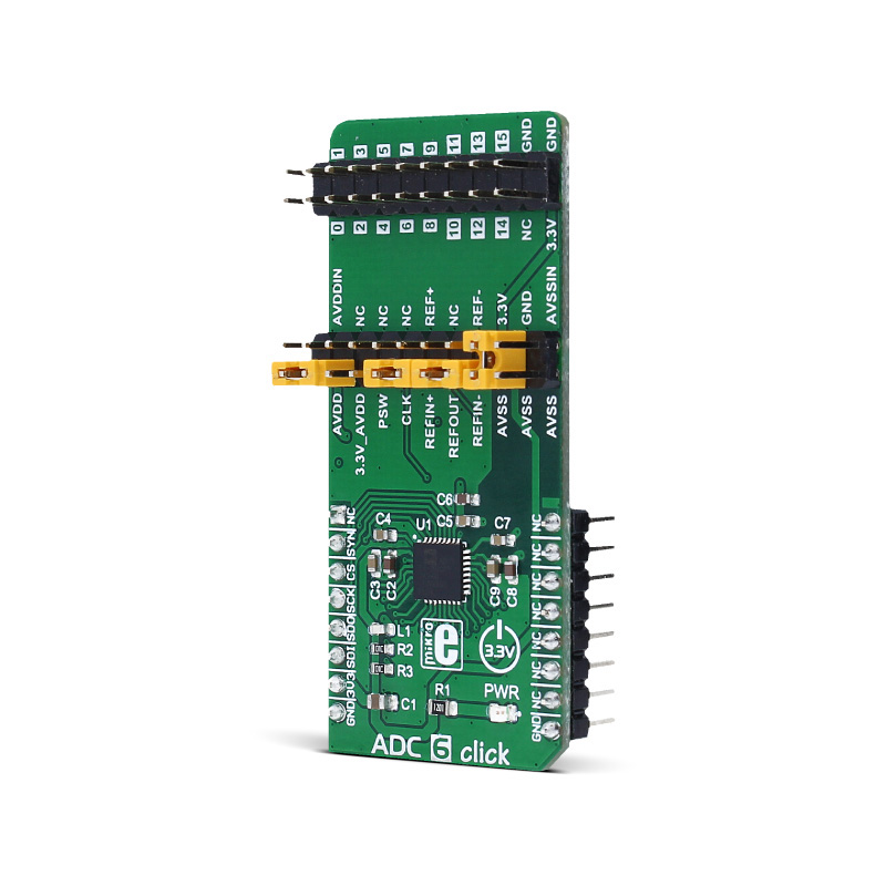
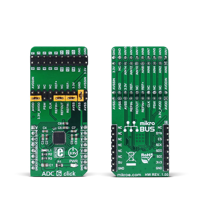
ADC 6 click is an advanced 24bit multichannel analog to digital converter (ADC), with 8 fully differential or 15 single ended/pseudo differential sampling inputs, and very flexible routing capabilities.

No Abuse Reported

Do you want to subscribe in order to receive notifications regarding "ADC 6 click" changes.

Do you want to unsubscribe in order to stop receiving notifications regarding "ADC 6 click" changes.

Do you want to report abuse regarding "ADC 6 click".

  • mikroSDK Library 2.0.0.0
  • Comments (0)
DOWNLOAD LINK RELATED COMPILER CONTAINS
mikroBasic PRO for ARM
  • lib
  • src
  • exa
  • hlp
  • hex
  • sch
  • pcb
  • doc
mikroBasic PRO for AVR
  • lib
  • src
  • exa
  • hlp
  • hex
  • sch
  • pcb
  • doc
mikroBasic PRO for dsPIC30/33 & PIC24
  • lib
  • src
  • exa
  • hlp
  • hex
  • sch
  • pcb
  • doc
mikroBasic PRO for FT90x
  • lib
  • src
  • exa
  • hlp
  • hex
  • sch
  • pcb
  • doc
mikroBasic PRO for PIC
  • lib
  • src
  • exa
  • hlp
  • hex
  • sch
  • pcb
  • doc
mikroBasic PRO for PIC32
  • lib
  • src
  • exa
  • hlp
  • hex
  • sch
  • pcb
  • doc
mikroC PRO for ARM
  • lib
  • src
  • exa
  • hlp
  • hex
  • sch
  • pcb
  • doc
mikroC PRO for AVR
  • lib
  • src
  • exa
  • hlp
  • hex
  • sch
  • pcb
  • doc
mikroC PRO for dsPIC30/33 & PIC24
  • lib
  • src
  • exa
  • hlp
  • hex
  • sch
  • pcb
  • doc
mikroC PRO for FT90x
  • lib
  • src
  • exa
  • hlp
  • hex
  • sch
  • pcb
  • doc
mikroC PRO for PIC
  • lib
  • src
  • exa
  • hlp
  • hex
  • sch
  • pcb
  • doc
mikroC PRO for PIC32
  • lib
  • src
  • exa
  • hlp
  • hex
  • sch
  • pcb
  • doc
mikroPascal PRO for ARM
  • lib
  • src
  • exa
  • hlp
  • hex
  • sch
  • pcb
  • doc
mikroPascal PRO for AVR
  • lib
  • src
  • exa
  • hlp
  • hex
  • sch
  • pcb
  • doc
mikroPascal PRO for dsPIC30/33 & PIC24
  • lib
  • src
  • exa
  • hlp
  • hex
  • sch
  • pcb
  • doc
mikroPascal PRO for FT90x
  • lib
  • src
  • exa
  • hlp
  • hex
  • sch
  • pcb
  • doc
mikroPascal PRO for PIC
  • lib
  • src
  • exa
  • hlp
  • hex
  • sch
  • pcb
  • doc
mikroPascal PRO for PIC32
  • lib
  • src
  • exa
  • hlp
  • hex
  • sch
  • pcb
  • doc

mikroSDK Library Blog

ADC 6 click

ADC 6 click

Native view of the ADC 6 click board.

View full image
ADC 6 click

ADC 6 click

Front and back view of the ADC 6 click board.

View full image

Library Description

Initializes and defines SPI bus driver and driver functions witch offer a choice to convert analog input voltage to 24-bit digital output value. Functions also offer a choice to choose witch channels we want use for positive and negative analog input by writting in configurations registers. Functions can read converted data in two modes, single read, where we must be sure that converting is done, or continuous read mode, where we only continuously read converted data without writting anything on SPI, not even an data register address. Library also defines commands witch help us to configure registers. Check documentation for more details.

Key functions :

void adc6_writeReg( const uint8_t register_address, const uint32_t transfer_data ) - Function writes data to determined register.

uint32_t adc6_readReg( const uint8_t register_address ) - Function reads data from determined register.

uint32_t adc6_continuousReadData( void ) - Function continuously reads data from Data register without writting anything on SPI.

uint32_t adc6_getADCData( const uint8_t mode ) - Function gets data from Data register in two possible modes. In single read mode first checks ready bit, and when conversion is done (data is ready) reads data from register. In continuous read mode only reads data without writting anything on SPI bus.

Examples Description

The application is composed of three sections :

  • System Initialization - Initializes peripherals and pins.
  • Application Initialization - Initializes SPI bus driver and sets configuration witch enables channel 0, puts AIN0 on positive analog input and AIN1 on negative analog input, enables internal reference voltage (approximately 2.65V (AVDD = 3.3V)), and also enables bipolar operation mode and puts device on full power mode. When the ADC is configured for unipolar operation, the output code is natural (straight) binary with a zero differential input voltage resulting in a code of 0x00000000, a midscale voltage resulting in a code of 0x00800000, and a full-scale input voltage resulting in a code of 0x00FFFFFF. When the ADC is configured for bipolar operation, the output code is offset binary with a negative full-scale voltage resulting in a code of 0x00000000, a zero differential input voltage resulting in a code of 0x00800000, and a positive full-scale input voltage resulting in a code of 0x00FFFFFF.
  • Application Task - (code snippet) - Gets 24-bit converted data in single read mode and logs data on USB UART. Repeats operation every 500 ms.
void applicationTask()
{
 adc_value = adc6_getADCData( _ADC6_SINGLE_GET_DATA_MODE );
 LongWordToStr( adc_value, text );
 if ( tmp )
 {
 mikrobus_logWrite( "** The ADC value is: **", _LOG_LINE );
 tmp = 0;
 }
 mikrobus_logWrite( text, _LOG_LINE );

 Delay_ms( 500 );
}

Other mikroE Libraries used in the example:

  • Conversions
  • SPI
  • UART

Additional notes and information

Depending on the development board you are using, you may need USB UART click,  USB UART 2 click or RS232 click to connect to your PC, for development systems with no UART to USB interface available on the board. The terminal available in all MikroElektronika compilers, or any other terminal application of your choice, can be used to read the message.

ALSO FROM THIS AUTHOR

Analog Input Demo

0

The application demonstrates Analog input SDK functionality.

[Learn More]

6DOF IMU 17 Click

0

6DOF IMU 17 Click is a compact add-on board that contains a 6-axis inertial measurement unit. This board features the IIM-42652, a 6-axis SmartIndustrial™ MotionTracking device that supports an extended operating temperature range for industrial applications from TDK InvenSense. It combines a 3-axis gyroscope and a 3-axis accelerometer featuring a 2K-byte FIFO that can lower the traffic on the serial bus interface (SPI or I2C) and reduce power consumption by allowing the system processor to burst read sensor data and then go into a low-power mode.

[Learn More]

iqRF 2 Click

0

IQRF Click carries the DCTR-76DA RF transceiver, operating in the 868/916 MHz frequency.

[Learn More]