TOP Contributors

  1. MIKROE (2784 codes)
  2. Alcides Ramos (387 codes)
  3. Shawon Shahryiar (307 codes)
  4. jm_palomino (120 codes)
  5. Bugz Bensce (97 codes)
  6. S P (73 codes)
  7. dany (71 codes)
  8. MikroBUS.NET Team (35 codes)
  9. NART SCHINACKOW (34 codes)
  10. Armstrong Subero (27 codes)

Most Downloaded

  1. Timer Calculator (140168 times)
  2. FAT32 Library (72622 times)
  3. Network Ethernet Library (57644 times)
  4. USB Device Library (47957 times)
  5. Network WiFi Library (43554 times)
  6. FT800 Library (42942 times)
  7. GSM click (30140 times)
  8. mikroSDK (28670 times)
  9. PID Library (27057 times)
  10. microSD click (26552 times)
Libstock prefers package manager

Package Manager

We strongly encourage users to use Package manager for sharing their code on Libstock website, because it boosts your efficiency and leaves the end user with no room for error. [more info]

< Back
mikroSDK Library

Spectral click

Rating:

5

Author: MIKROE

Last Updated: 2018-03-26

Package Version: 1.0.0.0

mikroSDK Library: 1.0.0.0

Category: Optical

Downloaded: 3476 times

Not followed.

License: MIT license  

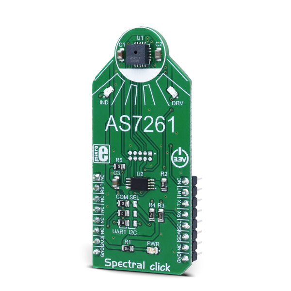
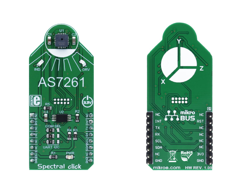
Spectral click is a light multispectral sensing device, which uses the state-of-the-art sensor IC for a very accurate true-color sensing. Spectral click provides a direct reading of the XYZ color coordinates, consistent with the CIE 1931 2. standard color space.

No Abuse Reported

Do you want to subscribe in order to receive notifications regarding "Spectral click" changes.

Do you want to unsubscribe in order to stop receiving notifications regarding "Spectral click" changes.

Do you want to report abuse regarding "Spectral click".

  • mikroSDK Library 2.0.0.0
  • Comments (0)

mikroSDK Library Blog

Spectral click

Spectral click

Native view of the Sprectral click board.

View full image
Spectral click

Spectral click

Front and back view of the Spectral click board.

View full image

Library Description

Library initializes and defines UART driver and functions witch offer a choice to providing direct XYZ color coordinates consistent with the CIE 1931.

  1. Standard Observer color coordinates. It also maps the XYZ coordinates to the x, y (Y) of the 2-dimensional color gamut and scales the coordinates to the CIE 1976 u’v’ coordinate system. The library provides accurate Correlated Color Temperature (CCT) measurements and provides color point deviation from the black body curve for white light color in the delta u’ v’ coordinate system. Check documentation for more details.


Key functions:

  • void spectral_getColor_Data(uint8_t *rsp, uint8_t *) - Reads calibrated X, Y, and Z color data.
  • void spectral_getXYsmall_Data(uint8_t *rsp, uint8_t *xyData) - Reads calibrated x and y for CIE 1931 color gamut.
  • uint8_t spectral_getLUX_Data(uint8_t *rsp) - Reads calibrated LUX value from the sensor.
  • uint8_t spectral_getCCT_Data(uint8_t *rsp) - Reads calibrated CCT value from the sensor.
  • void spectral_getUV_Data(uint8_t *rsp, uint16_t *uvData) - Reads calibrated u’, v’ and u, v for CIE 1976 color gamut.

Examples Description

The demo application is composed of three sections:

  • System Initialization - Initializes all necessary GPIO pins, UART used for
    the communcation with Spectral and UART used for infromation logging.
  • Application Initialization - Initializes driver, reset module and sends
    command for the default module configuration.
  • Application Task - (code snippet) - Sends the command to start reading data.
    Then logs to USBUART, six read values every 1 second.
void applicationTask()
{
 spectral_process();

 spectral_cmdSingle(&cmdData[0]);
 spectral_getData(&dataBuffer[0],&readData[0]);
 IntToStr(readData[0],text);
 mikrobus_logWrite( "-- X value:", _LOG_TEXT );
 mikrobus_logWrite( text, _LOG_LINE );

 IntToStr(readData[1],text);
 mikrobus_logWrite( "-- Y value:", _LOG_TEXT );
 mikrobus_logWrite( text, _LOG_LINE );

 IntToStr(readData[2],text);
 mikrobus_logWrite( "-- Z value:", _LOG_TEXT );
 mikrobus_logWrite( text, _LOG_LINE );

 IntToStr(readData[3],text);
 mikrobus_logWrite( "-- NIR value:", _LOG_TEXT );
 mikrobus_logWrite( text, _LOG_LINE );

 IntToStr(readData[4],text);
 mikrobus_logWrite( "-- D value:", _LOG_TEXT );
 mikrobus_logWrite( text, _LOG_LINE );

 IntToStr(readData[5],text);
 mikrobus_logWrite( "-- C value:", _LOG_TEXT );
 mikrobus_logWrite( text, _LOG_LINE );

 mikrobus_logWrite( "---------------------", _LOG_LINE );

 Delay_1sec();
}

Along with the demo application timer initialization functions are provided. Note that the timer is configured acording to the default develoment system and MCUs, changing the system or MCU may require an update of the timer init and timer ISR functions.

mikroE Libraries used in the example:

  • String
  • Conversions
  • UART

Additional notes and information

Depending on the development board you are using, you may need USB UART click,  USB UART 2 click or  RS232 click to connect to your PC, for development systems with no UART to USB interface available on the board. The terminal available in all MikroElektronika compilers, or any other terminal application of your choice, can be used to read the message.

ALSO FROM THIS AUTHOR

Expand 3 click

6

EXPAND 3 click is an accessory board in mikroBUS form factor. It includes an 8-channel programmable I/O expander DS2408 that communicates with the target board MCU through a 1-Wire interface (15.3 kbps or 100kbps).

[Learn More]

Accel 5 Click

0

Accel 5 Click features an ultra-low power triaxial accelerometer sensor, labeled as the BMA400. This Click board™ allows linear motion and gravitational force measurements in ranges of ±2 g, ±4 g, ±8, and ±16 g in three perpendicular axes.

[Learn More]

IR Grid 2 Click

0

IR Grid 2 Click is a thermal imaging sensor. It has an array of 768 very sensitive factory calibrated IR elements (pixels), arranged in 32 rows of 24 pixels. Each one of them is measuring an object temperature up to 300˚C within its local Field of View (FOV). The MLX90640ESF-BAB IR sensor used on this Click board™ has just four pins, and it is mounted inside of the industry standard TO39 package. It is equipped with 2Kbit of EEPROM for storing the compensation and calibration parameters.

[Learn More]