TOP Contributors

  1. MIKROE (2784 codes)
  2. Alcides Ramos (405 codes)
  3. Shawon Shahryiar (307 codes)
  4. jm_palomino (133 codes)
  5. Bugz Bensce (97 codes)
  6. S P (73 codes)
  7. dany (71 codes)
  8. MikroBUS.NET Team (35 codes)
  9. NART SCHINACKOW (34 codes)
  10. Armstrong Subero (27 codes)

Most Downloaded

  1. Timer Calculator (141452 times)
  2. FAT32 Library (74297 times)
  3. Network Ethernet Library (58836 times)
  4. USB Device Library (48909 times)
  5. Network WiFi Library (44679 times)
  6. FT800 Library (44214 times)
  7. GSM click (30933 times)
  8. mikroSDK (29802 times)
  9. PID Library (27403 times)
  10. microSD click (27333 times)
Libstock prefers package manager

Package Manager

We strongly encourage users to use Package manager for sharing their code on Libstock website, because it boosts your efficiency and leaves the end user with no room for error. [more info]

< Back
mikroSDK Library

Nano Power click

Rating:

5

Author: MIKROE

Last Updated: 2018-05-30

Package Version: 1.0.0.0

mikroSDK Library: 1.0.0.0

Category: Boost

Downloaded: 5031 times

Not followed.

License: MIT license  

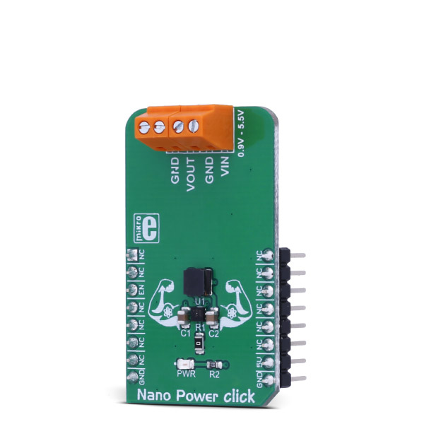
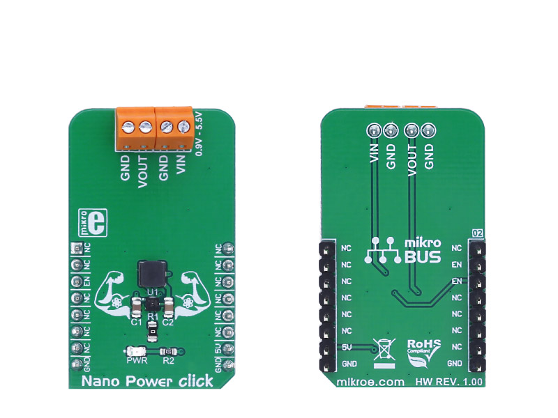
Nano Power click is a boost (step-up) DC-DC converter click with extremely high efficiency and very low input voltage, aimed at the low power IoT market and battery-powered sensors and other devices.

No Abuse Reported

Do you want to subscribe in order to receive notifications regarding "Nano Power click" changes.

Do you want to unsubscribe in order to stop receiving notifications regarding "Nano Power click" changes.

Do you want to report abuse regarding "Nano Power click".

  • mikroSDK Library 2.0.0.0
  • Comments (0)
DOWNLOAD LINK RELATED COMPILER CONTAINS
mikroBasic PRO for ARM
  • lib
  • src
  • exa
  • hlp
  • hex
  • sch
  • pcb
  • doc
mikroBasic PRO for AVR
  • lib
  • src
  • exa
  • hlp
  • hex
  • sch
  • pcb
  • doc
mikroBasic PRO for dsPIC30/33 & PIC24
  • lib
  • src
  • exa
  • hlp
  • hex
  • sch
  • pcb
  • doc
mikroBasic PRO for FT90x
  • lib
  • src
  • exa
  • hlp
  • hex
  • sch
  • pcb
  • doc
mikroBasic PRO for PIC
  • lib
  • src
  • exa
  • hlp
  • hex
  • sch
  • pcb
  • doc
mikroBasic PRO for PIC32
  • lib
  • src
  • exa
  • hlp
  • hex
  • sch
  • pcb
  • doc
mikroC PRO for ARM
  • lib
  • src
  • exa
  • hlp
  • hex
  • sch
  • pcb
  • doc
mikroC PRO for AVR
  • lib
  • src
  • exa
  • hlp
  • hex
  • sch
  • pcb
  • doc
mikroC PRO for dsPIC30/33 & PIC24
  • lib
  • src
  • exa
  • hlp
  • hex
  • sch
  • pcb
  • doc
mikroC PRO for FT90x
  • lib
  • src
  • exa
  • hlp
  • hex
  • sch
  • pcb
  • doc
mikroC PRO for PIC
  • lib
  • src
  • exa
  • hlp
  • hex
  • sch
  • pcb
  • doc
mikroC PRO for PIC32
  • lib
  • src
  • exa
  • hlp
  • hex
  • sch
  • pcb
  • doc
mikroPascal PRO for ARM
  • lib
  • src
  • exa
  • hlp
  • hex
  • sch
  • pcb
  • doc
mikroPascal PRO for AVR
  • lib
  • src
  • exa
  • hlp
  • hex
  • sch
  • pcb
  • doc
mikroPascal PRO for dsPIC30/33 & PIC24
  • lib
  • src
  • exa
  • hlp
  • hex
  • sch
  • pcb
  • doc
mikroPascal PRO for FT90x
  • lib
  • src
  • exa
  • hlp
  • hex
  • sch
  • pcb
  • doc
mikroPascal PRO for PIC
  • lib
  • src
  • exa
  • hlp
  • hex
  • sch
  • pcb
  • doc
mikroPascal PRO for PIC32
  • lib
  • src
  • exa
  • hlp
  • hex
  • sch
  • pcb
  • doc

mikroSDK Library Blog

Nano Power click

Nano Power click

Native view of the Nano Power click board.

View full image
Nano Power click

Nano Power click

Front and back view of the Nano Power click board.

View full image

Library Description

Library initializes and defines GPIO driver and performs control of device voltage.
For more details check the documentation.

Key functions:

  • void nanopw_enableDevice( const uint8_t state ) - The function allows or blocks the input voltage (enables or disables device).

Example description

The application is composed of three sections:

  • System Initialization -  Initializes ENABLE (RST) pin as an output.
  • Application Initialization - Initializes the GPIO driver.
  • Application Task - (code snippet) - Turns the device on for 5 seconds and then turns the device off for 10 seconds. Afterward, the output voltage starts to fall.
    When the input voltage rises from 0.8V to 5.5V, the output voltage rises from 5.1V to 5.25V. When the input voltage is less than 0.8V, the output voltage is less than 5V.
void applicationTask()
{
 nanopw_enableDevice( _NANOPW_ENABLE_DEVICE );
 Delay_ms( 5000 );
 nanopw_enableDevice( _NANOPW_DISABLE_DEVICE );
 Delay_ms( 10000 );
}


Additional notes and information

Depending on the development board you are using, you may need USB UART clickUSB UART 2 click or RS232 click to connect to your PC, for development systems with no UART to USB interface available on the board. The terminal available in all MikroElektronika compilers, or any other terminal application of your choice, can be used to read the message.

ALSO FROM THIS AUTHOR

Hz to V 2 click

5

HZ to V 2 click is a device that can convert input frequency of the signal with virtually any wave shape to a DC voltage output, with a level proportional to the input frequency.

[Learn More]

MCP2518FD Click

0

MCP2518FD Click is a compact add-on board representing a complete CAN solution used as a control node in a CAN network. This board features the MCP2518FD, an external CAN FD controller with an SPI interface, and a high-speed CAN transceiver, the ATA6563, both from Microchip. The ATA6563, a low-level physical layer IC (PHY), provides a physical connection with the CAN bus itself, while the CAN controller MCP2518FD represents an interface between the MCU and the PHY. It features three operating modes with dedicated fail-safe features, remote wake-up via CAN, and ideally passive behavior when powered off on the CAN bus. This Click board™ is suitable for developing a wide range of automotive diagnostic applications, even on MCUs that do not natively support CAN interface.

[Learn More]

Color 2 click

1

Color 2 click carries the ISL29125 RGB color light sensor. It detects red, green and blue in a variety of lighting conditions, outputting 16-bit resolution data in a 5.7m lux-10,000 lux measuring range. The board communicates with the target MCU through the mikroBUSâ„¢ I2C interface (SCL and SDA pins).

[Learn More]