TOP Contributors

  1. MIKROE (2784 codes)
  2. Alcides Ramos (405 codes)
  3. Shawon Shahryiar (307 codes)
  4. jm_palomino (133 codes)
  5. Bugz Bensce (97 codes)
  6. S P (73 codes)
  7. dany (71 codes)
  8. MikroBUS.NET Team (35 codes)
  9. NART SCHINACKOW (34 codes)
  10. Armstrong Subero (27 codes)

Most Downloaded

  1. Timer Calculator (142093 times)
  2. FAT32 Library (75352 times)
  3. Network Ethernet Library (59524 times)
  4. USB Device Library (49548 times)
  5. Network WiFi Library (45341 times)
  6. FT800 Library (44957 times)
  7. GSM click (31467 times)
  8. mikroSDK (30515 times)
  9. microSD click (27834 times)
  10. PID Library (27628 times)
Libstock prefers package manager

Package Manager

We strongly encourage users to use Package manager for sharing their code on Libstock website, because it boosts your efficiency and leaves the end user with no room for error. [more info]

< Back
mikroSDK Library

Driver click

Rating:

5

Author: MIKROE

Last Updated: 2018-08-07

Package Version: 1.0.0.0

mikroSDK Library: 1.0.0.0

Category: Stepper

Downloaded: 5174 times

Not followed.

License: MIT license  

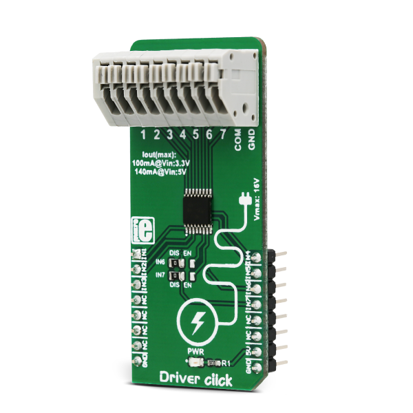
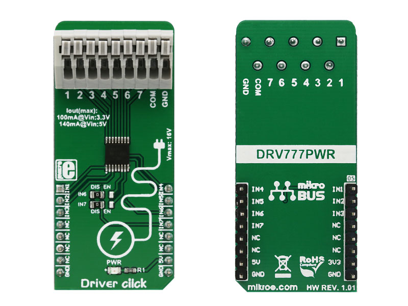
Driver click features an IC with seven integrated high-current sink drivers drivers, which can be used to drive a wide range of loads via simple parallel interface.

No Abuse Reported

Do you want to subscribe in order to receive notifications regarding "Driver click" changes.

Do you want to unsubscribe in order to stop receiving notifications regarding "Driver click" changes.

Do you want to report abuse regarding "Driver click".

  • mikroSDK Library 2.0.0.0
  • Comments (1)
DOWNLOAD LINK RELATED COMPILER CONTAINS
mikroBasic PRO for ARM
  • lib
  • src
  • exa
  • hlp
  • hex
  • sch
  • pcb
  • doc
mikroBasic PRO for AVR
  • lib
  • src
  • exa
  • hlp
  • hex
  • sch
  • pcb
  • doc
mikroBasic PRO for dsPIC30/33 & PIC24
  • lib
  • src
  • exa
  • hlp
  • hex
  • sch
  • pcb
  • doc
mikroBasic PRO for FT90x
  • lib
  • src
  • exa
  • hlp
  • hex
  • sch
  • pcb
  • doc
mikroBasic PRO for PIC
  • lib
  • src
  • exa
  • hlp
  • hex
  • sch
  • pcb
  • doc
mikroBasic PRO for PIC32
  • lib
  • src
  • exa
  • hlp
  • hex
  • sch
  • pcb
  • doc
mikroC PRO for ARM
  • lib
  • src
  • exa
  • hlp
  • hex
  • sch
  • pcb
  • doc
mikroC PRO for AVR
  • lib
  • src
  • exa
  • hlp
  • hex
  • sch
  • pcb
  • doc
mikroC PRO for dsPIC30/33 & PIC24
  • lib
  • src
  • exa
  • hlp
  • hex
  • sch
  • pcb
  • doc
mikroC PRO for FT90x
  • lib
  • src
  • exa
  • hlp
  • hex
  • sch
  • pcb
  • doc
mikroC PRO for PIC
  • lib
  • src
  • exa
  • hlp
  • hex
  • sch
  • pcb
  • doc
mikroC PRO for PIC32
  • lib
  • src
  • exa
  • hlp
  • hex
  • sch
  • pcb
  • doc
mikroPascal PRO for ARM
  • lib
  • src
  • exa
  • hlp
  • hex
  • sch
  • pcb
  • doc
mikroPascal PRO for AVR
  • lib
  • src
  • exa
  • hlp
  • hex
  • sch
  • pcb
  • doc
mikroPascal PRO for dsPIC30/33 & PIC24
  • lib
  • src
  • exa
  • hlp
  • hex
  • sch
  • pcb
  • doc
mikroPascal PRO for FT90x
  • lib
  • src
  • exa
  • hlp
  • hex
  • sch
  • pcb
  • doc
mikroPascal PRO for PIC
  • lib
  • src
  • exa
  • hlp
  • hex
  • sch
  • pcb
  • doc
mikroPascal PRO for PIC32
  • lib
  • src
  • exa
  • hlp
  • hex
  • sch
  • pcb
  • doc

mikroSDK Library Blog

Driver click

Driver click

Native view of the Driver click board.

View full image
Driver click

Driver click

Front and back view of the Driver click board.

View full image

Library Description

Library performs the control of the output pins (OUT1 - OUT7) by setting input pins (IN1 - IN7).
For more details check the documentation.

Key functions :

  • void driver_setIN1( uint8_t state ) - Function determines state of output 1 (OUT1).

Example description

The application is composed of three sections :

  • System Initialization - Initializes peripherals and pins.
  • Application Initialization - Initializes GPIO driver and selects which inputs will be set in operation. Bits from 0 to 6 (selectIN) select inputs from IN1 to IN7, respectively.
  • Application Task - (code snippet) - Performs cycles in which selected inputs will be turned on for pulse width delay time one by one. When one input is turned on, he will be turned off after the desired delay time before the next input be turned on.
void applicationTask()
{
 temp = 1;

 for (count = 0; count < 7; count++)
 {
 switch (selectIN & temp)
 {
 case 0x01 :
 {
 driver_setIN1( enableIN );
 Delay_ms( pulseWidth );
 driver_setIN1( disableIN );
 break;
 }
 case 0x02 :
 {
 driver_setIN2( enableIN );
 Delay_ms( pulseWidth );
 driver_setIN2( disableIN );
 break;
 }
 case 0x04 :
 {
 driver_setIN3( enableIN );
 Delay_ms( pulseWidth );
 driver_setIN3( disableIN );
 break;
 }
 case 0x08 :
 {
 driver_setIN4( enableIN );
 Delay_ms( pulseWidth );
 driver_setIN4( disableIN );
 break;
 }
 case 0x10 :
 {
 driver_setIN5( enableIN );
 Delay_ms( pulseWidth );
 driver_setIN5( disableIN );
 break;
 }
 case 0x20 :
 {
 driver_setIN6( enableIN );
 Delay_ms( pulseWidth );
 driver_setIN6( disableIN );
 break;
 }
 case 0x40 :
 {
 driver_setIN7( enableIN );
 Delay_ms( pulseWidth );
 driver_setIN7( disableIN );
 break;
 }
 default :
 {
 break;
 }
 }

 temp <<= 1;
 }
}

Additional notes and information

Depending on the development board you are using, you may need USB UART clickUSB UART 2 click or RS232 click to connect to your PC, for development systems with no UART to USB interface available on the board. The terminal available in all MikroElektronika compilers, or any other terminal application of your choice, can be used to read the message.

ALSO FROM THIS AUTHOR

I2C 1-Wire 2 Click

0

I2C 1-Wire 2 Click is a compact add-on board bridging I2C master interfaces with 1-Wire slave devices, ideal for simplifying complex communication protocols. This board features the DS2485, an advanced 1-Wire master with memory from Analog Devices. It features adjustable internal timers for precise 1-Wire signal management, relieving the host processor of timing-sensitive operations, and supports standard and overdrive communication speeds.

[Learn More]

Multi Stepper TB67S109 Click

0

Multi Stepper Click is a compact add-on board that contains a bipolar stepper motor driver. This board features the TB67S109AFTG, CLOCK-in controlled bipolar stepping motor driver from Toshiba Semiconductor. It supports a PWM constant-current control drive and allows from full-step up to 1/32 steps resolution for less motor noise and smoother control. It has a wide operating voltage range of 10V to 47V with an output current capacity of 2.8A in addition to several built-in error detection circuits.

[Learn More]

Water Detect 2 Click

0

Water Detect 2 Click is a compact add-on board that can detect the presence/flow of a liquid in a clear tube. This board features the OPB350L250, a tube liquid sensor from TT Electronics. Water Detect 2 Click has multiple output states and can recognize fluid present, no fluid present, and no tube present. This sensor excepts 1/4” tubing (6.3mm) as an outside diameter of the clear tubes, regardless of the direction of the liquid’s flow.

[Learn More]