TOP Contributors

  1. MIKROE (2784 codes)
  2. Alcides Ramos (405 codes)
  3. Shawon Shahryiar (307 codes)
  4. jm_palomino (133 codes)
  5. Bugz Bensce (97 codes)
  6. S P (73 codes)
  7. dany (71 codes)
  8. MikroBUS.NET Team (35 codes)
  9. NART SCHINACKOW (34 codes)
  10. Armstrong Subero (27 codes)

Most Downloaded

  1. Timer Calculator (141318 times)
  2. FAT32 Library (74154 times)
  3. Network Ethernet Library (58737 times)
  4. USB Device Library (48834 times)
  5. Network WiFi Library (44544 times)
  6. FT800 Library (44119 times)
  7. GSM click (30857 times)
  8. mikroSDK (29699 times)
  9. PID Library (27359 times)
  10. microSD click (27273 times)
Libstock prefers package manager

Package Manager

We strongly encourage users to use Package manager for sharing their code on Libstock website, because it boosts your efficiency and leaves the end user with no room for error. [more info]

< Back
mikroSDK Library

OPTO 2 click

Rating:

5

Author: MIKROE

Last Updated: 2018-05-14

Package Version: 1.0.0.0

mikroSDK Library: 1.0.0.0

Category: Optocoupler

Downloaded: 4972 times

Not followed.

License: MIT license  

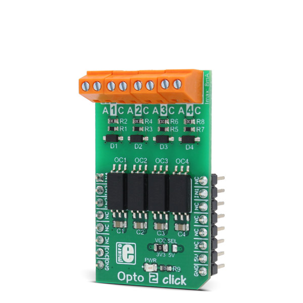
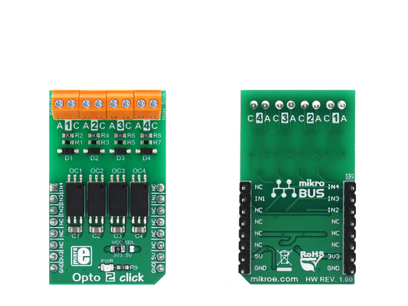
Opto 2 click is an optical isolator used to provide an optical galvanic isolation of sensitive lines.

No Abuse Reported

Do you want to subscribe in order to receive notifications regarding "OPTO 2 click" changes.

Do you want to unsubscribe in order to stop receiving notifications regarding "OPTO 2 click" changes.

Do you want to report abuse regarding "OPTO 2 click".

  • mikroSDK Library 2.0.0.0
  • Comments (0)
DOWNLOAD LINK RELATED COMPILER CONTAINS
mikroBasic PRO for ARM
  • lib
  • src
  • exa
  • hlp
  • hex
  • sch
  • pcb
  • doc
mikroBasic PRO for AVR
  • lib
  • src
  • exa
  • hlp
  • hex
  • sch
  • pcb
  • doc
mikroBasic PRO for dsPIC30/33 & PIC24
  • lib
  • src
  • exa
  • hlp
  • hex
  • sch
  • pcb
  • doc
mikroBasic PRO for FT90x
  • lib
  • src
  • exa
  • hlp
  • hex
  • sch
  • pcb
  • doc
mikroBasic PRO for PIC
  • lib
  • src
  • exa
  • hlp
  • hex
  • sch
  • pcb
  • doc
mikroBasic PRO for PIC32
  • lib
  • src
  • exa
  • hlp
  • hex
  • sch
  • pcb
  • doc
mikroC PRO for ARM
  • lib
  • src
  • exa
  • hlp
  • hex
  • sch
  • pcb
  • doc
mikroC PRO for AVR
  • lib
  • src
  • exa
  • hlp
  • hex
  • sch
  • pcb
  • doc
mikroC PRO for dsPIC30/33 & PIC24
  • lib
  • src
  • exa
  • hlp
  • hex
  • sch
  • pcb
  • doc
mikroC PRO for FT90x
  • lib
  • src
  • exa
  • hlp
  • hex
  • sch
  • pcb
  • doc
mikroC PRO for PIC
  • lib
  • src
  • exa
  • hlp
  • hex
  • sch
  • pcb
  • doc
mikroC PRO for PIC32
  • lib
  • src
  • exa
  • hlp
  • hex
  • sch
  • pcb
  • doc
mikroPascal PRO for ARM
  • lib
  • src
  • exa
  • hlp
  • hex
  • sch
  • pcb
  • doc
mikroPascal PRO for AVR
  • lib
  • src
  • exa
  • hlp
  • hex
  • sch
  • pcb
  • doc
mikroPascal PRO for dsPIC30/33 & PIC24
  • lib
  • src
  • exa
  • hlp
  • hex
  • sch
  • pcb
  • doc
mikroPascal PRO for FT90x
  • lib
  • src
  • exa
  • hlp
  • hex
  • sch
  • pcb
  • doc
mikroPascal PRO for PIC
  • lib
  • src
  • exa
  • hlp
  • hex
  • sch
  • pcb
  • doc
mikroPascal PRO for PIC32
  • lib
  • src
  • exa
  • hlp
  • hex
  • sch
  • pcb
  • doc

mikroSDK Library Blog

Opto 2 click

Opto 2 click

Native view of the Opto 2 click board.

View full image
Opto 2 click

Opto 2 click

Front and back view of the Opto 2 click board.

View full image

Library Description

The library performs the check procedure for the desired outputs (OUT1 - OUT4). For more details check the documentation.

Key functions:

  • uint8_t opto2_checkOut1( void ) - The function checks the state of the OUT1 pin.

Examples Description

The demo application is composed of three sections:

  • System Initialization - Initializes peripherals and pins.
  • Application Initialization -  Initializes GPIO driver and selects the outputs (OUT1 - OUT4) which state be checked.
  • Application Task - (code snippet) - Performs the check procedure for selected outputs and logs the states from the outputs on USB UART. Repeats the check procedure every 2 seconds.
     
void applicationTask()
{
 tmp = 1;

 for (cnt = 0; cnt < 4; cnt++)
 {
 switch (selOutput & tmp)
 {
 case 0x01 :
 {
 checkOutput = opto2_checkOut1();

 if (checkOutput == 0)
 {
 mikrobus_logWrite( "OUT1 is low", _LOG_LINE );
 }
 else
 {
 mikrobus_logWrite( "OUT1 is high", _LOG_LINE );
 }
 break;
 }
 case 0x02 :
 {
 checkOutput = opto2_checkOut2();

 if (checkOutput == 0)
 {
 mikrobus_logWrite( "OUT2 is low", _LOG_LINE );
 }
 else
 {
 mikrobus_logWrite( "OUT2 is high", _LOG_LINE );
 }
 break;
 }
 case 0x04 :
 {
 checkOutput = opto2_checkOut3();

 if (checkOutput == 0)
 {
 mikrobus_logWrite( "OUT3 is low", _LOG_LINE );
 }
 else
 {
 mikrobus_logWrite( "OUT3 is high", _LOG_LINE );
 }
 break;
 }
 case 0x08 :
 {
 checkOutput = opto2_checkOut4();

 if (checkOutput == 0)
 {
 mikrobus_logWrite( "OUT4 is low", _LOG_LINE );
 }
 else
 {
 mikrobus_logWrite( "OUT4 is high", _LOG_LINE );
 }
 break;
 }
 default :
 {
 break;
 }
 }

 tmp <<= 1;
 }
 mikrobus_logWrite( "", _LOG_LINE );

 Delay_ms( 2000 );
}
  • void opto2_setLogger( uint8_t selOut1, uint8_t selOut2, uint8_t selOut3, uint8_t selOut4 ) - Determines the outputs that be checked and logged on USB UART terminal. If selOutx is 1, the corresponding output will be included in check procedure.vAnd if selOutx is 0, that output will not be included in check procedure and will not be logged on UART.

mikroE Libraries used in the example:

  • UART

Additional notes and information

Depending on the development board you are using, you may need USB UART click,  USB UART 2 click or  RS232 click to connect to your PC, for development systems with no UART to USB interface available on the board. The terminal available in all MikroElektronika compilers, or any other terminal application of your choice, can be used to read the message.

ALSO FROM THIS AUTHOR

Buck 8 Click

0

Buck 8 Click is a high efficiency, wide voltage range, and high current synchronous step down (buck) DC-DC converter, featuring two enhanced modes that can be used to drive lighter loads with increased efficiency.

[Learn More]

PWR Meter click

5

PWR Meter click is a power measurement Click board, capable of measuring voltage and current through the load, connected to either AC or DC power source.

[Learn More]

Multi Stepper TB62261 Click

0

Multi Stepper Click is a compact add-on board that contains a bipolar stepper motor driver. This board features the TB62261FTG, a PHASE-in controlled bipolar stepping motor driver from Toshiba Semiconductor. It supports a PWM constant-current control drive and full-, half-, and quarter-step operation for less motor noise and smoother control. It has a wide operating voltage range of 10V to 38V with an output current capacity of 1.2A in addition to several built-in error detection circuits.

[Learn More]