TOP Contributors

  1. MIKROE (2784 codes)
  2. Alcides Ramos (405 codes)
  3. Shawon Shahryiar (307 codes)
  4. jm_palomino (133 codes)
  5. Bugz Bensce (97 codes)
  6. S P (73 codes)
  7. dany (71 codes)
  8. MikroBUS.NET Team (35 codes)
  9. NART SCHINACKOW (34 codes)
  10. Armstrong Subero (27 codes)

Most Downloaded

  1. Timer Calculator (142008 times)
  2. FAT32 Library (75243 times)
  3. Network Ethernet Library (59469 times)
  4. USB Device Library (49488 times)
  5. Network WiFi Library (45264 times)
  6. FT800 Library (44871 times)
  7. GSM click (31414 times)
  8. mikroSDK (30400 times)
  9. microSD click (27775 times)
  10. PID Library (27613 times)
Libstock prefers package manager

Package Manager

We strongly encourage users to use Package manager for sharing their code on Libstock website, because it boosts your efficiency and leaves the end user with no room for error. [more info]

< Back
mikroSDK Library

Oximeter click

Rating:

5

Author: MIKROE

Last Updated: 2018-07-20

Package Version: 1.0.0.0

mikroSDK Library: 1.0.0.0

Category: Biometrics

Downloaded: 5415 times

Not followed.

License: MIT license  

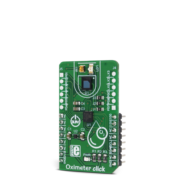
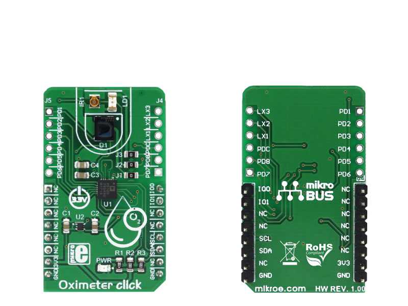
Oximeter click is a versatile photometric Click board, perfectly suited for measuring the blood oxygen saturation. It employs ADPD105, a highly configurable photometric front end (AFE) device from Analog Devices.

No Abuse Reported

Do you want to subscribe in order to receive notifications regarding "Oximeter click" changes.

Do you want to unsubscribe in order to stop receiving notifications regarding "Oximeter click" changes.

Do you want to report abuse regarding "Oximeter click".

  • mikroSDK Library 2.0.0.0
  • Comments (0)
DOWNLOAD LINK RELATED COMPILER CONTAINS
mikroBasic PRO for ARM
  • lib
  • src
  • exa
  • hlp
  • hex
  • sch
  • pcb
  • doc
mikroBasic PRO for AVR
  • lib
  • src
  • exa
  • hlp
  • hex
  • sch
  • pcb
  • doc
mikroBasic PRO for dsPIC30/33 & PIC24
  • lib
  • src
  • exa
  • hlp
  • hex
  • sch
  • pcb
  • doc
mikroBasic PRO for FT90x
  • lib
  • src
  • exa
  • hlp
  • hex
  • sch
  • pcb
  • doc
mikroBasic PRO for PIC
  • lib
  • src
  • exa
  • hlp
  • hex
  • sch
  • pcb
  • doc
mikroBasic PRO for PIC32
  • lib
  • src
  • exa
  • hlp
  • hex
  • sch
  • pcb
  • doc
mikroC PRO for ARM
  • lib
  • src
  • exa
  • hlp
  • hex
  • sch
  • pcb
  • doc
mikroC PRO for AVR
  • lib
  • src
  • exa
  • hlp
  • hex
  • sch
  • pcb
  • doc
mikroC PRO for dsPIC30/33 & PIC24
  • lib
  • src
  • exa
  • hlp
  • hex
  • sch
  • pcb
  • doc
mikroC PRO for FT90x
  • lib
  • src
  • exa
  • hlp
  • hex
  • sch
  • pcb
  • doc
mikroC PRO for PIC
  • lib
  • src
  • exa
  • hlp
  • hex
  • sch
  • pcb
  • doc
mikroC PRO for PIC32
  • lib
  • src
  • exa
  • hlp
  • hex
  • sch
  • pcb
  • doc
mikroPascal PRO for ARM
  • lib
  • src
  • exa
  • hlp
  • hex
  • sch
  • pcb
  • doc
mikroPascal PRO for AVR
  • lib
  • src
  • exa
  • hlp
  • hex
  • sch
  • pcb
  • doc
mikroPascal PRO for dsPIC30/33 & PIC24
  • lib
  • src
  • exa
  • hlp
  • hex
  • sch
  • pcb
  • doc
mikroPascal PRO for FT90x
  • lib
  • src
  • exa
  • hlp
  • hex
  • sch
  • pcb
  • doc
mikroPascal PRO for PIC
  • lib
  • src
  • exa
  • hlp
  • hex
  • sch
  • pcb
  • doc
mikroPascal PRO for PIC32
  • lib
  • src
  • exa
  • hlp
  • hex
  • sch
  • pcb
  • doc

mikroSDK Library Blog

Oximeter click

Oximeter click

Native view of the Oximeter click board.

View full image
Oximeter click

Oximeter click

Front and back view of the Oximeter click board.

View full image

Library Description

The library can communicate with the device via I2C driver by writing to the registers and by reading from the registers, including data registers. The library has the ability to measure the level of oxygen (O2) in the blood, something like blood pressure. Library also can configure the device to works in two Time Slot Mode independently with different configurations. For more details check the documentation.

Key functions:

  • uint8_t oxim_writeReg( uint8_t register_address, uint16_t transfer_data ) - The function writes 16-bit data to the register.
  • uint8_t oxim_setTimeSlotA( uint8_t enableSlotA, uint8_t enablePhotodiode, uint8_t enableLED, uint8_t setMode ) - The function performs the configuration for Time Slot A and enables the interrupt for this Slot.
  • uint8_t oxim_enableChannels( uint8_t selectChannel ) - The function determines which channel/channels be enabled.
  • void oxim_readData( uint32_t *channResults, uint8_t resultMode ) - Function reads data in the desired mode for determined Slot.

Example description

The application is composed of three sections :

  • System Initialization - Initializes peripherals and pins.
  • Application Initialization - Initializes I2C driver and performs the device configuration which puts Time Slot Ain enabled mode and LEDX2 (IR diode) to the active state. On Oximeter click the photodiode is connected on PD1 input, and because we will observe the Channel 1 in this example (CH1 is enabled). Before the device configuration, the SW reset will be performed and in this way, we will put the registers in the initial state.
  • Application Task - (code snippet) - Gets data when IR diode (LEDX2) is enabled, and after that gets data when LED diode(LEDX1) is enabled. Repeats operation 10 times and then calculates the average value for both results. This results logs on the serial plot as graphic view. Note: For this example you must have the serial plot aplication.The IR diode is internal connected on LEDX2 input, and the LED diode is internal connected on LEDX1 input.The photodiode is internal connected on PD1 input.When we want to perform some register configuration we must first put the device in Program Operating Mode, then we canset the desired register to the desired value, and when we finished, then we can put the device back to the Normal Operating Mode.
void applicationTask()
{
 oxim_plotDisplay();
}

Additional Functions :

  • void oxim_plotDisplay() - Makes the average value of 10 samples when IR diode and LED diode is enabled alternately, and logs results on serial plot as graphic view.
  • void oxim_uartDisplay() - Gets 100 samples of data when IR diode is enabled, and then gets 100 samples of data when LED diode is enabled and after that logs this 100 samples of data for both diode parallel on USB UART as graphic view.
  • void oxim_logsResults() - Gets data which is determined in aplicationinit configuration and logs result on USB UART.

Other mikroE Libraries used in the example:

  • Conversions
  • I2C
  • UART

Additional notes and information

Depending on the development board you are using, you may need USB UART clickUSB UART 2 click or RS232 click to connect to your PC, for development systems with no UART to USB interface available on the board. The terminal available in all MikroElektronika compilers, or any other terminal application of your choice, can be used to read the message.

ALSO FROM THIS AUTHOR

Speed Sense Click

0

Speed Sense Click is a compact add-on board that allows you to measure the speed and rotation of a spinning object. This board features the A17501, a dual output differential speed and direction sensor from Allegro Microsystems. It has a high-speed switching bandwidth of up to 40kHz for two different signals. The sensor has two independent output channels with options for high-resolution XOR speed, pulse, and direction protocol.

[Learn More]

RYB080I Click

0

RYB080I Click is a compact add-on board for seamless Bluetooth Low Energy (LE) communication in various wireless applications. This board features the RYB080I, a 2.4GHz Bluetooth 4.2/5.0 LE module with an integrated antenna from REYAX, based on the TI CC2640R2F ARM® Cortex®-M3 MCU. This module supports dual-device connectivity, operates in both Host and Client roles, and includes a metal cover for EMI protection, ensuring stable performance even in noisy environments. With support for the Generic Attribute Profile (GATT) and easy setup via REYAX AT commands, integration into diverse systems is simplified.

[Learn More]

H-Bridge 10 Click

0

H-Bridge 10 Click is a compact add-on board containing H-bridge outputs that let you control a DC motor to go backward or forward. This board features the MP6523, a triple, half-bridge, DMOS, output driver with integrated power MOSFETs that can drive up to three different loads from Monolithic Power Systems (MPS). The MP6523 is rated for an operating voltage range from 7V to 28V. It is SPI-configurable and has various diagnostic functions. Complete protection features include short-circuit protection (SCP), under-voltage protection (UVP), and thermal shutdown, alongside an onboard power supply existence-check circuit. This Click board™ is suitable as a multiple brushed DC motor driver for driving various loads in automotive and industrial applications, and more.

[Learn More]