TOP Contributors

  1. MIKROE (2779 codes)
  2. Alcides Ramos (376 codes)
  3. Shawon Shahryiar (307 codes)
  4. jm_palomino (118 codes)
  5. Bugz Bensce (97 codes)
  6. S P (73 codes)
  7. dany (71 codes)
  8. MikroBUS.NET Team (35 codes)
  9. NART SCHINACKOW (34 codes)
  10. Armstrong Subero (27 codes)

Most Downloaded

  1. Timer Calculator (139565 times)
  2. FAT32 Library (72041 times)
  3. Network Ethernet Library (57255 times)
  4. USB Device Library (47615 times)
  5. Network WiFi Library (43219 times)
  6. FT800 Library (42566 times)
  7. GSM click (29930 times)
  8. mikroSDK (28292 times)
  9. PID Library (26933 times)
  10. microSD click (26309 times)
Libstock prefers package manager

Package Manager

We strongly encourage users to use Package manager for sharing their code on Libstock website, because it boosts your efficiency and leaves the end user with no room for error. [more info]

< Back
mikroSDK Library

Air quality 5 click

Rating:

10

Author: MIKROE

Last Updated: 2018-06-28

Package Version: 1.0.0.0

mikroSDK Library: 1.0.0.0

Category: Gas

Downloaded: 5244 times

Not followed.

License: MIT license  

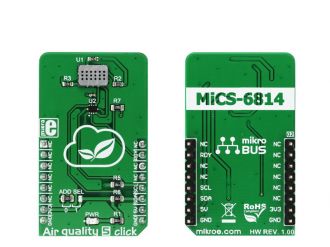
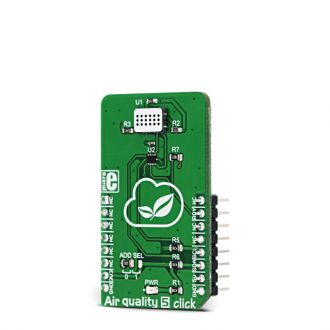
Air quality 5 click is a triple MOS sensor on a single Click board, which can detect gas pollution for a number of different gases. The onboard sensor is specially designed to detect the pollution from automobile exhausts as well as the gas pollution from the industrial or agricultural industry.

No Abuse Reported

Do you want to subscribe in order to receive notifications regarding "Air quality 5 click" changes.

Do you want to unsubscribe in order to stop receiving notifications regarding "Air quality 5 click" changes.

Do you want to report abuse regarding "Air quality 5 click".
  • mikroSDK Library 2.0.0.0
  • Comments (0)
DOWNLOAD LINK RELATED COMPILER CONTAINS
mikroBasic PRO for ARM
  • lib
  • src
  • exa
  • hlp
  • hex
  • sch
  • pcb
  • doc
mikroBasic PRO for AVR
  • lib
  • src
  • exa
  • hlp
  • hex
  • sch
  • pcb
  • doc
mikroBasic PRO for dsPIC30/33 & PIC24
  • lib
  • src
  • exa
  • hlp
  • hex
  • sch
  • pcb
  • doc
mikroBasic PRO for FT90x
  • lib
  • src
  • exa
  • hlp
  • hex
  • sch
  • pcb
  • doc
mikroBasic PRO for PIC
  • lib
  • src
  • exa
  • hlp
  • hex
  • sch
  • pcb
  • doc
mikroBasic PRO for PIC32
  • lib
  • src
  • exa
  • hlp
  • hex
  • sch
  • pcb
  • doc
mikroC PRO for ARM
  • lib
  • src
  • exa
  • hlp
  • hex
  • sch
  • pcb
  • doc
mikroC PRO for AVR
  • lib
  • src
  • exa
  • hlp
  • hex
  • sch
  • pcb
  • doc
mikroC PRO for dsPIC30/33 & PIC24
  • lib
  • src
  • exa
  • hlp
  • hex
  • sch
  • pcb
  • doc
mikroC PRO for FT90x
  • lib
  • src
  • exa
  • hlp
  • hex
  • sch
  • pcb
  • doc
mikroC PRO for PIC
  • lib
  • src
  • exa
  • hlp
  • hex
  • sch
  • pcb
  • doc
mikroC PRO for PIC32
  • lib
  • src
  • exa
  • hlp
  • hex
  • sch
  • pcb
  • doc
mikroPascal PRO for ARM
  • lib
  • src
  • exa
  • hlp
  • hex
  • sch
  • pcb
  • doc
mikroPascal PRO for AVR
  • lib
  • src
  • exa
  • hlp
  • hex
  • sch
  • pcb
  • doc
mikroPascal PRO for dsPIC30/33 & PIC24
  • lib
  • src
  • exa
  • hlp
  • hex
  • sch
  • pcb
  • doc
mikroPascal PRO for FT90x
  • lib
  • src
  • exa
  • hlp
  • hex
  • sch
  • pcb
  • doc
mikroPascal PRO for PIC
  • lib
  • src
  • exa
  • hlp
  • hex
  • sch
  • pcb
  • doc
mikroPascal PRO for PIC32
  • lib
  • src
  • exa
  • hlp
  • hex
  • sch
  • pcb
  • doc

mikroSDK Library Blog

Air quality 5 click

Air quality 5 click

Native view of the Air quality 5 click board.

View full image
Air quality 5 click

Air quality 5 click

Front and back view of the Air quality 5 click board.

View full image

Library Description

The library initializes and defines the I2C bus driver and drivers that offer a choice for writing data in registers and reading data from registers. The library includes functions for full initialization of the chip, reading 3 sensors (CO, NH3 and NO2 data). The user can check the state of the RDY pin indicating if that data is ready for reading.

Key functions:

  • void airq5_setConfiguration(uint16_t config) - The functions for configuration.
  • uint16_t airq5_readSensorData(uint16_t channel_data) - The functions for reading the sensor data.

Example description

The application is composed of three sections:

  • System Initialization -  Initializes I2C module and sets INT pin as INPUT.
  • Application Initialization - Initializes driver init and configuration chip.
  • Application Task - (code snippet) - Reads the values of CO, NH3 and NO2 sensor and logs data on USBUART every 500ms.
void applicationTask()
{
 NO2_sensorData = airq5_readSensorData(_AIRQ5_DATA_CHANNEL_NO2);
 NH3_sensorData = airq5_readSensorData(_AIRQ5_DATA_CHANNEL_NH3);
 CO_sensorData = airq5_readSensorData(_AIRQ5_DATA_CHANNEL_CO);

 IntToStr(NO2_sensorData, dataText);
 mikrobus_logWrite(" NO2 data: ", _LOG_TEXT);
 mikrobus_logWrite(dataText, _LOG_LINE);

 IntToStr(NH3_sensorData, dataText);
 mikrobus_logWrite(" NH3 data: ", _LOG_TEXT);
 mikrobus_logWrite(dataText, _LOG_LINE);

 IntToStr(CO_sensorData, dataText);
 mikrobus_logWrite(" CO data: ", _LOG_TEXT);
 mikrobus_logWrite(dataText, _LOG_LINE);

 mikrobus_logWrite(" -------- ", _LOG_LINE);
 Delay_ms( 500 );
}


Other MikroElektronika libraries used in the example:

  • Conversions
  • I2C
  • UART

Additional notes and information

Depending on the development board you are using, you may need USB UART clickUSB UART 2 click or RS232 click to connect to your PC, for development systems with no UART to USB interface available on the board. The terminal available in all MikroElektronika compilers, or any other terminal application of your choice, can be used to read the message.

ALSO FROM THIS AUTHOR

DIGI POT click

0

This program demonstrates the usage of single channel Digital Potentiometer (MCP4161) with 8 bit resolution. Voltage derived from PW pin is read by MCU's ADC. Scaled value is then displayed at PORTD LEDs. User can increase or decrease resitance by pressing buttons RB2 and RB3.&amp;lt;br/&amp;gt;

[Learn More]

7x10 G click

5

7x10 G click can be used for displaying letters on display with 7x5 font resolution. It carries a matrix of 70 green LEDs driven by a pair of 8-bit serial-in, parallel-out shift registers, a Darlington Transistor array and a Johnson counter.

[Learn More]

8x8 G Click

0

8x8 G Click is a 64 LED matrix display Click board™, composed of SMD LEDs organized in 8 rows by 8 columns. It has a digital brightness control in 16 steps, it can control every LED in the display matrix independently, it blanks the display on power up to eliminate glitches and it requires a single resistor to control the current through all the LEDs at once, which simplifies the design. 8x8 G Click uses a fast SPI communication protocol, allowing fast display response and no lag.

[Learn More]