TOP Contributors

  1. MIKROE (2784 codes)
  2. Alcides Ramos (403 codes)
  3. Shawon Shahryiar (307 codes)
  4. jm_palomino (132 codes)
  5. Bugz Bensce (97 codes)
  6. S P (73 codes)
  7. dany (71 codes)
  8. MikroBUS.NET Team (35 codes)
  9. NART SCHINACKOW (34 codes)
  10. Armstrong Subero (27 codes)

Most Downloaded

  1. Timer Calculator (140969 times)
  2. FAT32 Library (73515 times)
  3. Network Ethernet Library (58321 times)
  4. USB Device Library (48509 times)
  5. Network WiFi Library (44134 times)
  6. FT800 Library (43688 times)
  7. GSM click (30547 times)
  8. mikroSDK (29292 times)
  9. PID Library (27220 times)
  10. microSD click (26931 times)
Libstock prefers package manager

Package Manager

We strongly encourage users to use Package manager for sharing their code on Libstock website, because it boosts your efficiency and leaves the end user with no room for error. [more info]

< Back
mikroSDK Library

H-Bridge click

Rating:

5

Author: MIKROE

Last Updated: 2018-05-25

Package Version: 1.0.0.0

mikroSDK Library: 1.0.0.0

Category: Stepper

Downloaded: 4602 times

Not followed.

License: MIT license  

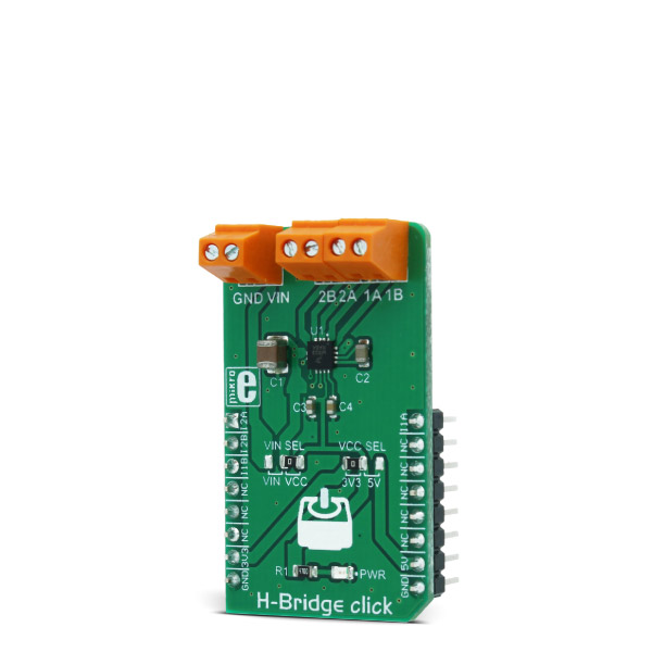
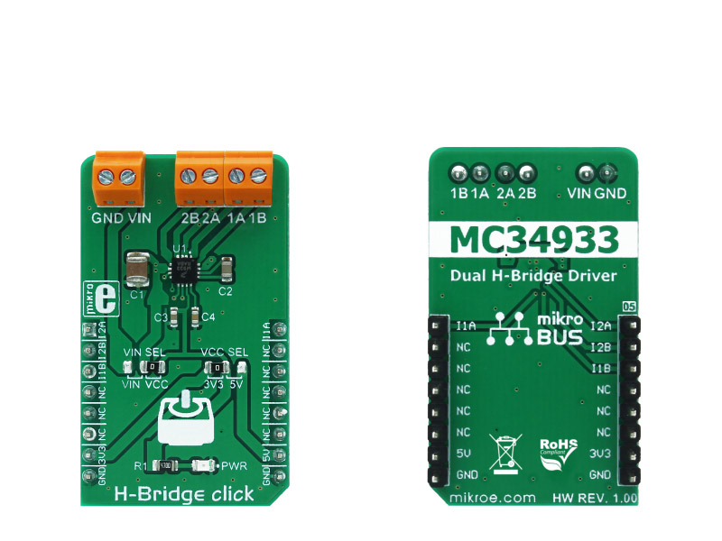
H-Bridge click is a high-efficiency dual H-bridge driver Click board, capable of providing reasonably high current while driving the connected load with up to 7V. Since the used driver IC has two full H-bridge channels, this Click board is an ideal solution for driving smaller bipolar stepper motors.

No Abuse Reported

Do you want to subscribe in order to receive notifications regarding "H-Bridge click" changes.

Do you want to unsubscribe in order to stop receiving notifications regarding "H-Bridge click" changes.

Do you want to report abuse regarding "H-Bridge click".

  • mikroSDK Library 2.0.0.0
  • Comments (0)
DOWNLOAD LINK RELATED COMPILER CONTAINS
mikroBasic PRO for ARM
  • lib
  • src
  • exa
  • hlp
  • hex
  • sch
  • pcb
  • doc
mikroBasic PRO for AVR
  • lib
  • src
  • exa
  • hlp
  • hex
  • sch
  • pcb
  • doc
mikroBasic PRO for dsPIC30/33 & PIC24
  • lib
  • src
  • exa
  • hlp
  • hex
  • sch
  • pcb
  • doc
mikroBasic PRO for FT90x
  • lib
  • src
  • exa
  • hlp
  • hex
  • sch
  • pcb
  • doc
mikroBasic PRO for PIC
  • lib
  • src
  • exa
  • hlp
  • hex
  • sch
  • pcb
  • doc
mikroBasic PRO for PIC32
  • lib
  • src
  • exa
  • hlp
  • hex
  • sch
  • pcb
  • doc
mikroC PRO for ARM
  • lib
  • src
  • exa
  • hlp
  • hex
  • sch
  • pcb
  • doc
mikroC PRO for AVR
  • lib
  • src
  • exa
  • hlp
  • hex
  • sch
  • pcb
  • doc
mikroC PRO for dsPIC30/33 & PIC24
  • lib
  • src
  • exa
  • hlp
  • hex
  • sch
  • pcb
  • doc
mikroC PRO for FT90x
  • lib
  • src
  • exa
  • hlp
  • hex
  • sch
  • pcb
  • doc
mikroC PRO for PIC
  • lib
  • src
  • exa
  • hlp
  • hex
  • sch
  • pcb
  • doc
mikroC PRO for PIC32
  • lib
  • src
  • exa
  • hlp
  • hex
  • sch
  • pcb
  • doc
mikroPascal PRO for ARM
  • lib
  • src
  • exa
  • hlp
  • hex
  • sch
  • pcb
  • doc
mikroPascal PRO for AVR
  • lib
  • src
  • exa
  • hlp
  • hex
  • sch
  • pcb
  • doc
mikroPascal PRO for dsPIC30/33 & PIC24
  • lib
  • src
  • exa
  • hlp
  • hex
  • sch
  • pcb
  • doc
mikroPascal PRO for FT90x
  • lib
  • src
  • exa
  • hlp
  • hex
  • sch
  • pcb
  • doc
mikroPascal PRO for PIC
  • lib
  • src
  • exa
  • hlp
  • hex
  • sch
  • pcb
  • doc
mikroPascal PRO for PIC32
  • lib
  • src
  • exa
  • hlp
  • hex
  • sch
  • pcb
  • doc

mikroSDK Library Blog

H-Bridge click

H-Bridge click

Native view of the H-Bridge click board.

View full image
H-Bridge click

H-Bridge click

Front and back view of the H-Bridge click board.

View full image

Library Description

The library carries everything needed for stepper motor control including speed
and acceleration setup. The library is also adjustable so that it's possible to work on a different amount of ticks per second. Also, speed and acceleration can be provided in float format. The buffer used for the movement calculation is defined by the user, so this library can be adjusted for MCUs with very limited RAM resources. Check the documentation for more details how to use it.

Key functions:

uint8_t hbridge_setSpeed( float minSpeed, float maxSpeed, float accelRatio, T_HBRIDGE_OBJ obj ) - Setup motor speed.

uint8_t hbridge_setRoute( const uint8_t direction, uint32_t steps, T_HBRIDGE_OBJ obj ) - Setup new route. 

void hbridge_start( T_HBRIDGE_OBJ obj ) - Starts the motor movement.

void hbridge_setOutput( uint8_t state ) - Function puts the all four outputs in the desired state.

Examples Description

The application is composed of three sections:

  • System Initialization - Initializes all GPIO pins found on H_Bridge Click and timer to 1ms interrupt.
  • Application Initialization - The first segment initializes driver and stepper control. Second segment setup movement limits, maximum and minimum speed, and acceleration ratio. The third segment enables the motor and set up a new route which will be called from application task.
  • Application Task - (code snippet) - Sequentially moves the motor. The first part of sequence executes movement until the end. The second part stops the motor movement after one second and continues the sequence after two seconds.
void applicationTask()
{
 hbridge_start( (T_HBRIDGE_OBJ)&myStepper );
 while( myStepper.status.running )
 {
 hbridge_process( (T_HBRIDGE_OBJ)&myStepper );
 }
 Delay_ms( 1000 );
}

Additional notes and information

Depending on the development board you are using, you may need USB UART clickUSB UART 2 click or RS232 click to connect to your PC, for development systems with no UART to USB interface available on the board. The terminal available in all MikroElektronika compilers, or any other terminal application of your choice, can be used to read the message.

ALSO FROM THIS AUTHOR

RTC Click

0

RTC Click is an accessory board in mikroBus™ form factor. It features the PCF8583 serial real-time clock (RTC)

[Learn More]

V to Hz 3 Click

0

V to Hz 3 Click is a compact add-on board that converts an analog voltage input signal into a specific frequency pulse wave signal. This board features the AD7740, an ultrasmall synchronous voltage-to-frequency converter from Analog Devices. The AD7740 has a linear response, so applying a voltage from 3V up to 5V on its VIN terminal will generate the pulse with a frequency linearly proportional to the input voltage. It contains an integrated 2.5V bandgap reference defining the span of the VFC and can be overdriven using an external reference. The full-scale output frequency is synchronous with the input clock signal provided by the LTC6903 programmable oscillator, with a maximum input frequency of 1MHz. Based on the analog input value, the output frequency goes from 10% to 90% of the input frequency.

[Learn More]

Light Click

0

This application return the ambient light intensity

[Learn More]