TOP Contributors

  1. MIKROE (2784 codes)
  2. Alcides Ramos (405 codes)
  3. Shawon Shahryiar (307 codes)
  4. jm_palomino (133 codes)
  5. Bugz Bensce (97 codes)
  6. S P (73 codes)
  7. dany (71 codes)
  8. MikroBUS.NET Team (35 codes)
  9. NART SCHINACKOW (34 codes)
  10. Armstrong Subero (27 codes)

Most Downloaded

  1. Timer Calculator (141454 times)
  2. FAT32 Library (74299 times)
  3. Network Ethernet Library (58837 times)
  4. USB Device Library (48909 times)
  5. Network WiFi Library (44679 times)
  6. FT800 Library (44214 times)
  7. GSM click (30933 times)
  8. mikroSDK (29803 times)
  9. PID Library (27403 times)
  10. microSD click (27333 times)
Libstock prefers package manager

Package Manager

We strongly encourage users to use Package manager for sharing their code on Libstock website, because it boosts your efficiency and leaves the end user with no room for error. [more info]

< Back
mikroSDK Library

CAN SPI 3.3V click

Rating:

0

Author: MIKROE

Last Updated: 2019-08-01

Package Version: 1.0.0.1

mikroSDK Library: 1.0.0.0

Category: CAN

Downloaded: 12793 times

Followed by: 2 users

License: MIT license  

This is code that shows simple connection of two CAN SPI modules with SN65HVD230.<br/>
Messages are sent by pressing PortB buttons and received message can be seen on PortD LEDs.<br/>

No Abuse Reported

Do you want to subscribe in order to receive notifications regarding "CAN SPI 3.3V click" changes.

Do you want to unsubscribe in order to stop receiving notifications regarding "CAN SPI 3.3V click" changes.

Do you want to report abuse regarding "CAN SPI 3.3V click".

  • Information
  • Comments (0)
DOWNLOAD LINK RELATED COMPILER CONTAINS
mikroBasic PRO for ARM
  • lib
  • src
  • exa
  • hlp
  • hex
  • sch
  • pcb
  • doc
mikroBasic PRO for AVR
  • lib
  • src
  • exa
  • hlp
  • hex
  • sch
  • pcb
  • doc
mikroBasic PRO for dsPIC30/33 & PIC24
  • lib
  • src
  • exa
  • hlp
  • hex
  • sch
  • pcb
  • doc
mikroBasic PRO for FT90x
  • lib
  • src
  • exa
  • hlp
  • hex
  • sch
  • pcb
  • doc
mikroBasic PRO for PIC
  • lib
  • src
  • exa
  • hlp
  • hex
  • sch
  • pcb
  • doc
mikroBasic PRO for PIC32
  • lib
  • src
  • exa
  • hlp
  • hex
  • sch
  • pcb
  • doc
mikroC PRO for ARM
  • lib
  • src
  • exa
  • hlp
  • hex
  • sch
  • pcb
  • doc
mikroC PRO for AVR
  • lib
  • src
  • exa
  • hlp
  • hex
  • sch
  • pcb
  • doc
mikroC PRO for dsPIC30/33 & PIC24
  • lib
  • src
  • exa
  • hlp
  • hex
  • sch
  • pcb
  • doc
mikroC PRO for FT90x
  • lib
  • src
  • exa
  • hlp
  • hex
  • sch
  • pcb
  • doc
mikroC PRO for PIC
  • lib
  • src
  • exa
  • hlp
  • hex
  • sch
  • pcb
  • doc
mikroC PRO for PIC32
  • lib
  • src
  • exa
  • hlp
  • hex
  • sch
  • pcb
  • doc
mikroPascal PRO for ARM
  • lib
  • src
  • exa
  • hlp
  • hex
  • sch
  • pcb
  • doc
mikroPascal PRO for AVR
  • lib
  • src
  • exa
  • hlp
  • hex
  • sch
  • pcb
  • doc
mikroPascal PRO for dsPIC30/33 & PIC24
  • lib
  • src
  • exa
  • hlp
  • hex
  • sch
  • pcb
  • doc
mikroPascal PRO for FT90x
  • lib
  • src
  • exa
  • hlp
  • hex
  • sch
  • pcb
  • doc
mikroPascal PRO for PIC
  • lib
  • src
  • exa
  • hlp
  • hex
  • sch
  • pcb
  • doc
mikroPascal PRO for PIC32
  • lib
  • src
  • exa
  • hlp
  • hex
  • sch
  • pcb
  • doc

mikroSDK Library Blog

CAN SPI 3.3V click

CAN SPI 3.3V click

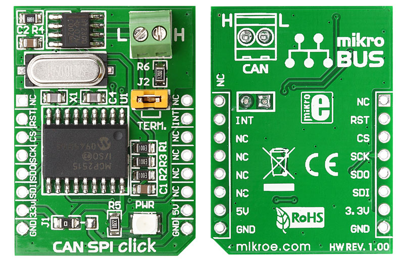
Front and back view of CAN SPI 3.3V click board designed in mikroBUS form factor. mikroBUS is specially designed pinout standard with SPI, I2C, Analog, UART, Interrupt, PWM, Reset and Power supply pins.

View full image

Library Description

The library covers all the necessary functions to control CAN SPI 3v3 click board.

Key functions:

  • void canspi3v3_hwReset() - Hardware reset function.
  • uint8_t canspi3v3_getInterrupt() - Get interrupt state function.

The application is composed of the three sections :

  • System Initialization - Initializes GPIO, SPI, and LOG structures, sets INT pin as an input, CS and RST pin as output and start to write log.
  • Application Initialization - Initialization driver enables - SPI, initialize external CANSPI module, also write log.
  • Application Task - This is an example which demonstrates the use of CAN SPI 3v3 Click board. In this example, we show a simple connection of two CAN SPI 3v3 modules. Results are being sent to the Usart Terminal where you can track their changes. All data logs write on usb uart changes for every 1 sec.
void applicationTask()
{
    char dataRxTx[ 8 ];
    uint8_t dataRxLen;
    uint8_t msgRcvd;
    uint8_t dataTx;
    uint32_t idRx;

    dataTx = 0xAB;

    msgRcvd = CANSPIRead( &idRx , &dataRxTx , &dataRxLen, &canRcvFlags );

    if ( msgRcvd )
    {
        mikrobus_logWrite( &dataRxTx, _LOG_BYTE );
        Delay_1sec();
    }

//    CANSPIWrite( id2nd, dataTx, 1, canSendFlags );
//    mikrobus_logWrite( "MESSAGE SENT", _LOG_LINE );
//    Delay_1sec();
}

Other mikroE Libraries used in the example:

  • SPI
  • CAN_SPI
  • UART

Additional notes and informations

Depending on the development board you are using, you may need USB UART clickUSB UART 2 click or RS232 click to connect to your PC, for development systems with no UART to USB interface available on the board. The terminal available in all MikroElektronika compilers, or any other terminal application of your choice, can be used to read the message.

ALSO FROM THIS AUTHOR

Heart Rate 9 click

5

The Heart Rate 9 click is a Click boardâ„¢ which features PIC16F1779 8-bit MCU and SFH 7060 heart rate and pulse oximetry monitoring sensor. This Click boar employs a very sensitive analog front-end IC with high dynamic range, which ensures accurate and reliable readings.

[Learn More]

Thunder Click

0

Thunder Click features AS3935 lightning sensor as well as MA5532 coil antenna. It detects the presence and proximity of potentially hazardous lightning activity in the vicinity and provides estimated distance to the center of the storm. It can also provide information on the noise level. Thunder Click communicates with the target board microcontroller via SPI and INT lines. The board is designed to use 3.3V or 5V power supply. LED diode (GREEN) indicates the presence of power supply.

[Learn More]

RTC 3 click

5

RTC3 click carries BQ32000, a real time clock/calendar with an integrated trickle charge circuit for automatic switchover to a backup power supply (the circuit maintains the backup charge with an onboard super capacitor). The clock frequency is derived from an onboard 32.768KHz oscillator.

[Learn More]