We strongly encourage users to use Package manager for sharing their code on Libstock website, because it boosts your efficiency and leaves the end user with no room for error. [more info]

Rating:
Author: MIKROE
Last Updated: 2018-09-07
Package Version: 1.0.0.0
mikroSDK Library: 1.0.0.0
Category: LTE IoT
Downloaded: 6684 times
Not followed.
License: MIT license
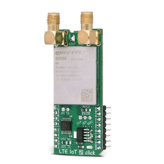
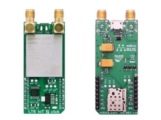
LTE IoT 2 click is a Click board that allows connection to the LTE networks, featuring Quectel BG96 LTE module, which offers two LTE technologies aimed at Machine to Machine communication (M2M) and Internet of Things (IoT).
Do you want to subscribe in order to receive notifications regarding "LTE IoT 2 click" changes.
Do you want to unsubscribe in order to stop receiving notifications regarding "LTE IoT 2 click" changes.
Do you want to report abuse regarding "LTE IoT 2 click".


The library carries generic command parser adopted for AT command based modules.
Generic parser
Key functions:
lteiot2_cmdSingle - Sends provided command to the modulelteiot2_setHandler - Handler assignation to the provied commandlteiot2_modulePower - Turn on moduleExample description
The application is composed of three sections:
This code snippet shows how generic parser should be properly initialized. Before initialization module must be turned on and add to that hardware flow control should be also
Commands :
Command: ATI, product information
Command: AT+IPR=115200;&W, set baudrate
Command: AT+QCFG="nbsibscramble",0, Enable scrambling
Command: AT+QCFG="band",0,0,80,1, set baud
Command: AT+QCFG="nwscanmode",3,1, Set LTE mode
Command: AT+QCFG="nwscanseq",030201,1, set priority NB1 > M1 > 2G
Command: AT+QCFG="iotopmode",1,1, select CAT-NB1
Command: AT+QCFG="servicedomain",1,1, Set PS domain
Command: AT+CGDCONT=1,"IP","internet", set APN provided
Command: AT+CFUN=1, Full functionality
Command: AT+COPS=1,2,"22001",0, set MCC and MNC provided
Command: AT+QIACT=1, activate PDP context
Command: AT+QIOPEN=1,0,"UDP","79.114.83.116",16666, create an UDP socket
Command: AT+QISENDEX=0,"48656C6C6F", Send message - Hello
void applicationInit()
{
// MODULE POWER ON
 lteiot2_hfcEnable( true );
 lteiot2_modulePower( true );

// MODULE INIT
 lteiot2_cmdSingle( &ATI[0] );
 lteiot2_cmdSingle( &AT_IPR[0] );
 lteiot2_cmdSingle( &AT_QCFG_1[0] );
 lteiot2_cmdSingle( &AT_QCFG_2[0] );
 lteiot2_cmdSingle( &AT_QCFG_3[0] );
 lteiot2_cmdSingle( &AT_QCFG_4[0] );
 lteiot2_cmdSingle( &AT_QCFG_5[0] );
 lteiot2_cmdSingle( &AT_QCFG_6[0] );
 lteiot2_cmdSingle( &AT_CGDCONT[0] );
 lteiot2_cmdSingle( &AT_CFUN[0] );
 lteiot2_cmdSingle( &AT_COPS[0] );
 lteiot2_cmdSingle( &AT_CGATT[0] );
 lteiot2_cmdSingle( &AT_CEREG[0] );
 lteiot2_cmdSingle( &AT_QIACT[0] );
 lteiot2_cmdSingle( &AT_QIOPEN[0] );
 lteiot2_cmdSingle( &AT_QISENDEX[0] );
}
Alongside with the demo application timer initialization functions are provided. Note that timer is configured acording to default development system and MCUs, changing the system or MCU may require an update of timer init and timer ISR functions.
Other MikroElektronika libraries used in the example:
Depending on the development board you are using, you may need USB UART click, USB UART 2 clickor RS232 click to connect to your PC, for development systems with no UART to USB interface available on the board. The terminal available in all MikroElektronika compilers, or any other terminal application of your choice, can be used to read the message.