TOP Contributors

  1. MIKROE (2784 codes)
  2. Alcides Ramos (387 codes)
  3. Shawon Shahryiar (307 codes)
  4. jm_palomino (120 codes)
  5. Bugz Bensce (97 codes)
  6. S P (73 codes)
  7. dany (71 codes)
  8. MikroBUS.NET Team (35 codes)
  9. NART SCHINACKOW (34 codes)
  10. Armstrong Subero (27 codes)

Most Downloaded

  1. Timer Calculator (140168 times)
  2. FAT32 Library (72622 times)
  3. Network Ethernet Library (57644 times)
  4. USB Device Library (47957 times)
  5. Network WiFi Library (43553 times)
  6. FT800 Library (42942 times)
  7. GSM click (30140 times)
  8. mikroSDK (28670 times)
  9. PID Library (27057 times)
  10. microSD click (26552 times)
Libstock prefers package manager

Package Manager

We strongly encourage users to use Package manager for sharing their code on Libstock website, because it boosts your efficiency and leaves the end user with no room for error. [more info]

< Back
mikroSDK Library

LTE IoT click

Rating:

5

Author: MIKROE

Last Updated: 2018-09-21

Package Version: 1.0.0.0

mikroSDK Library: 1.0.0.0

Category: LTE IoT

Downloaded: 4641 times

Not followed.

License: MIT license  

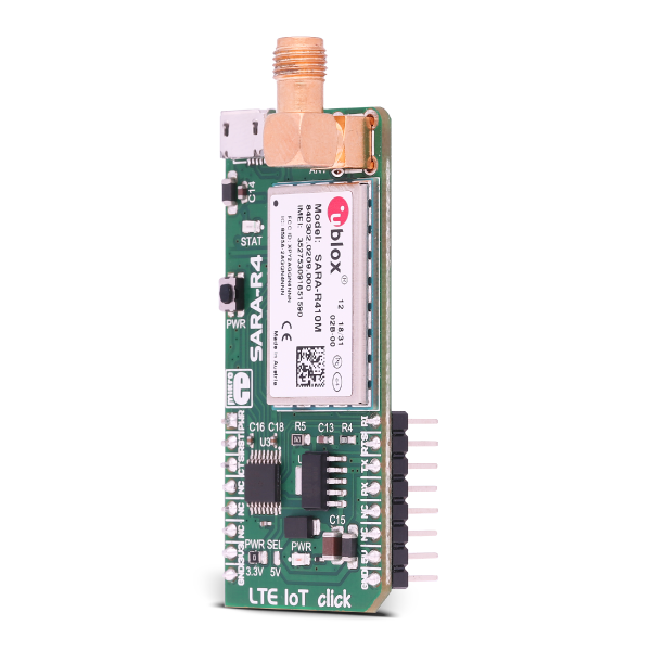
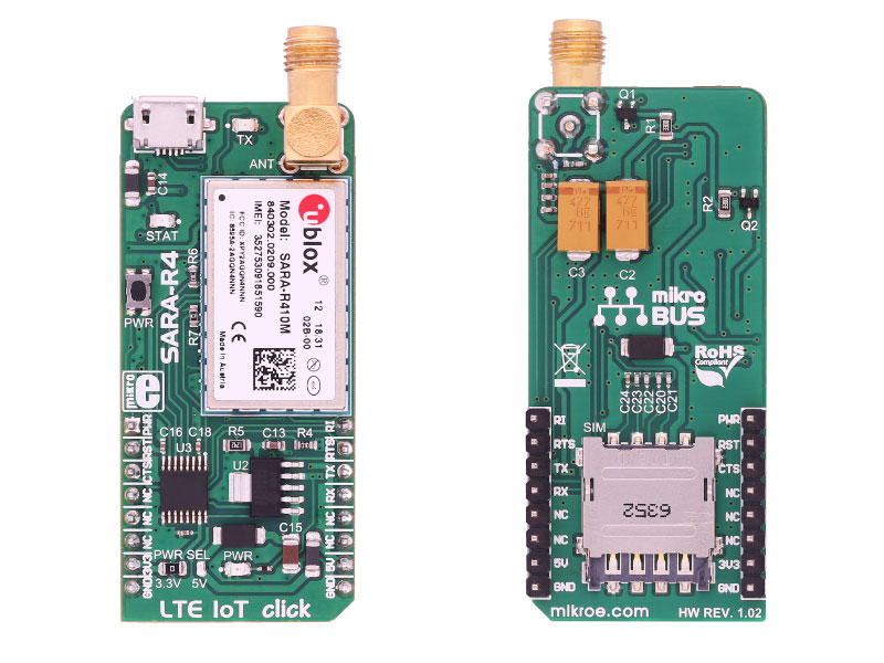
LTE IoT click is a Click board that allows connection to the LTE and 2G networks, featuring the compact form-factor SARA R410 LTE/2G module, which offers two LTE technologies aimed at Machine to Machine communication (M2M) and the Internet of Things (IoT).

No Abuse Reported

Do you want to subscribe in order to receive notifications regarding "LTE IoT click" changes.

Do you want to unsubscribe in order to stop receiving notifications regarding "LTE IoT click" changes.

Do you want to report abuse regarding "LTE IoT click".

  • mikroSDK Library 2.0.0.0
  • Comments (0)
DOWNLOAD LINK RELATED COMPILER CONTAINS
mikroBasic PRO for ARM
  • lib
  • src
  • exa
  • hlp
  • hex
  • sch
  • pcb
  • doc
mikroBasic PRO for AVR
  • lib
  • src
  • exa
  • hlp
  • hex
  • sch
  • pcb
  • doc
mikroBasic PRO for dsPIC30/33 & PIC24
  • lib
  • src
  • exa
  • hlp
  • hex
  • sch
  • pcb
  • doc
mikroBasic PRO for FT90x
  • lib
  • src
  • exa
  • hlp
  • hex
  • sch
  • pcb
  • doc
mikroBasic PRO for PIC
  • lib
  • src
  • exa
  • hlp
  • hex
  • sch
  • pcb
  • doc
mikroBasic PRO for PIC32
  • lib
  • src
  • exa
  • hlp
  • hex
  • sch
  • pcb
  • doc
mikroC PRO for ARM
  • lib
  • src
  • exa
  • hlp
  • hex
  • sch
  • pcb
  • doc
mikroC PRO for AVR
  • lib
  • src
  • exa
  • hlp
  • hex
  • sch
  • pcb
  • doc
mikroC PRO for dsPIC30/33 & PIC24
  • lib
  • src
  • exa
  • hlp
  • hex
  • sch
  • pcb
  • doc
mikroC PRO for FT90x
  • lib
  • src
  • exa
  • hlp
  • hex
  • sch
  • pcb
  • doc
mikroC PRO for PIC
  • lib
  • src
  • exa
  • hlp
  • hex
  • sch
  • pcb
  • doc
mikroC PRO for PIC32
  • lib
  • src
  • exa
  • hlp
  • hex
  • sch
  • pcb
  • doc
mikroPascal PRO for ARM
  • lib
  • src
  • exa
  • hlp
  • hex
  • sch
  • pcb
  • doc
mikroPascal PRO for AVR
  • lib
  • src
  • exa
  • hlp
  • hex
  • sch
  • pcb
  • doc
mikroPascal PRO for dsPIC30/33 & PIC24
  • lib
  • src
  • exa
  • hlp
  • hex
  • sch
  • pcb
  • doc
mikroPascal PRO for FT90x
  • lib
  • src
  • exa
  • hlp
  • hex
  • sch
  • pcb
  • doc
mikroPascal PRO for PIC
  • lib
  • src
  • exa
  • hlp
  • hex
  • sch
  • pcb
  • doc
mikroPascal PRO for PIC32
  • lib
  • src
  • exa
  • hlp
  • hex
  • sch
  • pcb
  • doc

mikroSDK Library Blog

LTE IoT click

LTE IoT click

Native view of the LTE IoT click board.

View full image
LTE IoT click

LTE IoT click

Front and back view of the LTE IoT click board.

View full image

Library Description

The application is composed of three sections :

System Initialization - Initializes all necessary GPIO pins, UART used for the communcation with LTE IOT 2 module and UART used for infromation logging
Application Initialization - Initializes driver, power on module and sends few command for the default module configuration Create UDP socket and sending message to UDP socket.

This code snippet shows how generic parser should be properly initialized. Before intialization module must be turned on and additionaly to that hardware  flow control should be also 

Commands :

Command : AT+CMEE=2 - Enables the cellular module to report verbose error result codes
Command : AT+CGATT? - Verifies the SARA-R4 module is attached to the network.
Command : AT+CEREG? - Verify the network registration status.
Command : AT+COPS=0 - Register the module on the network
Command : AT+COPS? - Read the operator name
Command : AT+USOCR=17 - Create a UDP socket.
Command : AT+USOST=0,"IP address",port,number character,"message" - Connecting and storing text on the server.
Command : AT+USORF=0,number character - Reading the message from the server
Command : AT+USOCL=0 - Closing the socket.

Example description

Click board wakes up from sleep. Some tests are performed. After the tests and after the data has been sent and received from the network the click board is placed into the sleep mode to its low power mode. All events that are executed inside of the application task are printed to the serial port.

// MODULE POWER ON
 lteiot_hfcEnable( true );
 lteiot_modulePower( true );

// MODULE INIT
 lteiot_cmdSingle( &_LTEIOT_AT[0] );
 lteiot_cmdSingle( &_LTEIOT_ATE1[0] );
 lteiot_cmdSingle( &_LTEIOT_AT_CMEE[0] );
 lteiot_cmdSingle( &_LTEIOT_AT_CGATT[0] );
 lteiot_cmdSingle( &_LTEIOT_AT_CEREG[0] );
 lteiot_cmdSingle( &_LTEIOT_AT_COPS[0] );
 lteiot_cmdSingle( &_LTEIOT_AT_COPS_1[0] );
 lteiot_cmdSingle( &_LTEIOT_AT_USOCR[0] );
 lteiot_cmdSingle( &_LTEIOT_AT_USOST[0] );
 lteiot_cmdSingle( &_LTEIOT_AT_USOCL[0] );

Alongside with the demo application timer initialization functions are provided. Note that timer is configured acording to default develoment system and MCUs, changing the system or MCU may require update of timer init and timer ISR  functions. 

Other MikroElektronika libraries used in the example:

  • String
  • Conversion

Depending on the development board you are using, you may need USB UART clickUSB UART 2 click or RS232 click to connect to your PC, for development systems with no UART to USB interface available on the board. The terminal available in all MikroElektronika compilers, or any other terminal application of your choice, can be used to read the message.

ALSO FROM THIS AUTHOR

BarGraph click - Cloud Demo

5

- The example contains all the necessary initializations and settings for a G2C click on a successful connection by Click Cloud. - BarGraph click (actuator) displays value of the counter that is settings on the Cloud. - This example demonstrate using the Actuator(counter) parser.

[Learn More]

13DOF 2 click

5

13DOF 2 click is an advanced 13-axis motion tracking Click board, which utilizes two different sensor ICs onboard: BME680, voc, humidity, pressure and temperature sensor and BMX160, a 9-axis sensor consisting of a 3-axis, low-g accelerometer, a low power 3-axis gyroscope and a 3-axis geomagnetic sensor.

[Learn More]

PAC1934 click

5

PAC1934 click carries the PAC1934 four channel DC power/energy monitor from Microchip. The click is designed to run on either 3.3V or 5V power supply. It communicates with the target microcontroller over an I2C interface.

[Learn More]