TOP Contributors

  1. MIKROE (2784 codes)
  2. Alcides Ramos (402 codes)
  3. Shawon Shahryiar (307 codes)
  4. jm_palomino (129 codes)
  5. Bugz Bensce (97 codes)
  6. S P (73 codes)
  7. dany (71 codes)
  8. MikroBUS.NET Team (35 codes)
  9. NART SCHINACKOW (34 codes)
  10. Armstrong Subero (27 codes)

Most Downloaded

  1. Timer Calculator (140769 times)
  2. FAT32 Library (73356 times)
  3. Network Ethernet Library (58200 times)
  4. USB Device Library (48385 times)
  5. Network WiFi Library (43977 times)
  6. FT800 Library (43538 times)
  7. GSM click (30467 times)
  8. mikroSDK (29170 times)
  9. PID Library (27169 times)
  10. microSD click (26848 times)
Libstock prefers package manager

Package Manager

We strongly encourage users to use Package manager for sharing their code on Libstock website, because it boosts your efficiency and leaves the end user with no room for error. [more info]

< Back
mikroSDK Library

Color 8 click

Rating:

5

Author: MIKROE

Last Updated: 2018-10-29

Package Version: 1.0.0.0

mikroSDK Library: 1.0.0.0

Category: Optical

Downloaded: 4526 times

Not followed.

License: MIT license  

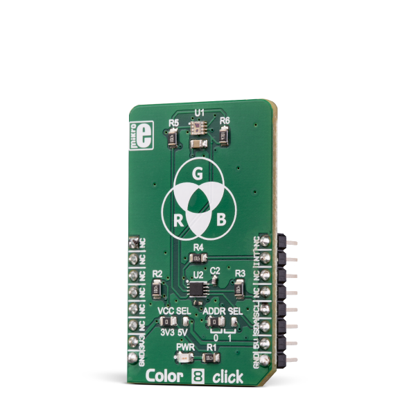
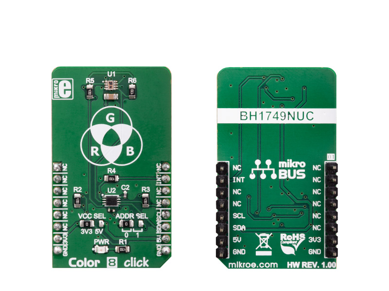
Color 8 click is a color-sensing Click board™, a part of our sensor Click board line. Sensing the color by utilizing ROHM’s BH1749NUC, an integrated color sensor IC, it comes in the package which also includes the mikroSDK software, a library with all the functions.

No Abuse Reported

Do you want to subscribe in order to receive notifications regarding "Color 8 click" changes.

Do you want to unsubscribe in order to stop receiving notifications regarding "Color 8 click" changes.

Do you want to report abuse regarding "Color 8 click".

  • mikroSDK Library 2.0.0.0
  • Comments (0)
DOWNLOAD LINK RELATED COMPILER CONTAINS
mikroBasic PRO for ARM
  • lib
  • src
  • exa
  • hlp
  • hex
  • sch
  • pcb
  • doc
mikroBasic PRO for AVR
  • lib
  • src
  • exa
  • hlp
  • hex
  • sch
  • pcb
  • doc
mikroBasic PRO for dsPIC30/33 & PIC24
  • lib
  • src
  • exa
  • hlp
  • hex
  • sch
  • pcb
  • doc
mikroBasic PRO for FT90x
  • lib
  • src
  • exa
  • hlp
  • hex
  • sch
  • pcb
  • doc
mikroBasic PRO for PIC
  • lib
  • src
  • exa
  • hlp
  • hex
  • sch
  • pcb
  • doc
mikroBasic PRO for PIC32
  • lib
  • src
  • exa
  • hlp
  • hex
  • sch
  • pcb
  • doc
mikroC PRO for ARM
  • lib
  • src
  • exa
  • hlp
  • hex
  • sch
  • pcb
  • doc
mikroC PRO for AVR
  • lib
  • src
  • exa
  • hlp
  • hex
  • sch
  • pcb
  • doc
mikroC PRO for dsPIC30/33 & PIC24
  • lib
  • src
  • exa
  • hlp
  • hex
  • sch
  • pcb
  • doc
mikroC PRO for FT90x
  • lib
  • src
  • exa
  • hlp
  • hex
  • sch
  • pcb
  • doc
mikroC PRO for PIC
  • lib
  • src
  • exa
  • hlp
  • hex
  • sch
  • pcb
  • doc
mikroC PRO for PIC32
  • lib
  • src
  • exa
  • hlp
  • hex
  • sch
  • pcb
  • doc
mikroPascal PRO for ARM
  • lib
  • src
  • exa
  • hlp
  • hex
  • sch
  • pcb
  • doc
mikroPascal PRO for AVR
  • lib
  • src
  • exa
  • hlp
  • hex
  • sch
  • pcb
  • doc
mikroPascal PRO for dsPIC30/33 & PIC24
  • lib
  • src
  • exa
  • hlp
  • hex
  • sch
  • pcb
  • doc
mikroPascal PRO for FT90x
  • lib
  • src
  • exa
  • hlp
  • hex
  • sch
  • pcb
  • doc
mikroPascal PRO for PIC
  • lib
  • src
  • exa
  • hlp
  • hex
  • sch
  • pcb
  • doc
mikroPascal PRO for PIC32
  • lib
  • src
  • exa
  • hlp
  • hex
  • sch
  • pcb
  • doc

mikroSDK Library Blog

Color 8 click

Color 8 click

Native view of the Color 8 click board.

View full image
Color 8 click

Color 8 click

Front and back view of the Color 8 click board.

View full image

Library Description

The library initializes and defines the I2C bus driver and drivers that offer a choice for writing data in register and reads data from register. The library includes function for configuration chip for measurement, function for reads one color and functions for light color value is received by calculating RGB value and conversions in HSL value. The user also has the function color8_getColor() which checks the color of the light.

Key functions:

  • void float color8_getColorValue() - Functions for read color value in HSL
  • void uint8_t color8_getColor(float color_value) - Function for set output voltage

Examples description

The application is composed of the three sections :

  • System Initialization - Initializes I2C module and sets INT pin as INPUT
  • Application Initialization - Initialization driver init and device configuration for start measurement
  • Application Task - (code snippet) - Reads RED, GREEEN, BLUE and IR data. Converts data to HSL value and return detect color. For a successful color test, place a click near the color of the monitor and detect the color on the screen.
void applicationTask()
{
    RED_data = color8_readData(_COLOR8_REG_RED_DATA);
    IntToStr(RED_data, demoText);
    mikrobus_logWrite(" RED data : ", _LOG_TEXT);
    mikrobus_logWrite(demoText, _LOG_LINE);
    
    GREEN_data = color8_readData(_COLOR8_REG_GREEN_DATA);
    IntToStr(GREEN_data, demoText);
    mikrobus_logWrite(" GREEN data : ", _LOG_TEXT);
    mikrobus_logWrite(demoText, _LOG_LINE);
    
    BLUE_data = color8_readData(_COLOR8_REG_BLUE_DATA);
    IntToStr(BLUE_data, demoText);
    mikrobus_logWrite(" BLUE data : ", _LOG_TEXT);
    mikrobus_logWrite(demoText, _LOG_LINE);
    
    IR_data = color8_readData(_COLOR8_REG_IR_DATA);
    IntToStr(IR_data, demoText);
    mikrobus_logWrite(" IR data : ", _LOG_TEXT);
    mikrobus_logWrite(demoText, _LOG_LINE);
    
    colorValue = color8_getColorValue();
    FloatToStr(colorValue, demoText);
    mikrobus_logWrite(" HSL color value : ", _LOG_TEXT);
    mikrobus_logWrite(demoText, _LOG_LINE);
    
    isColor = color8_getColor(colorValue);
    
    switch(isColor)
    {
        case 1:
        {
            mikrobus_logWrite("--- Color: ORANGE ", _LOG_LINE);
            break;
        }
        case 2:
        {
            mikrobus_logWrite("--- Color: RED ", _LOG_LINE);
            break;
        }
        case 3:
        {
            mikrobus_logWrite("--- Color: PINK ", _LOG_LINE);
            break;
        }
        case 4:
        {
            mikrobus_logWrite("--- Color: PURPLE ", _LOG_LINE);
            break;
        }
        case 5:
        {
            mikrobus_logWrite("--- Color: BLUE ", _LOG_LINE);
            break;
        }
        case 6:
        {
            mikrobus_logWrite("--- Color: CYAN ", _LOG_LINE);
            break;
        }
        case 7:
        {
            mikrobus_logWrite("--- Color: GREEN ", _LOG_LINE);
            break;
        }
        case 8:
        {
            mikrobus_logWrite("--- Color: YELLOW ", _LOG_LINE);
            break;
        }
        default:
        {
            break;
        }
    }
    Delay_100ms();
    
    mikrobus_logWrite("  ", _LOG_LINE);
    Delay_ms( 1000 );
}


Other mikroE Libraries used in the example:

  • I2C

Additional notes and information

Depending on the development board you are using, you may need USB UART clickUSB UART 2 click or RS232 click to connect to your PC, for development systems with no UART to USB interface available on the board. The terminal available in all MikroElektronika compilers, or any other terminal application of your choice, can be used to read the message.

ALSO FROM THIS AUTHOR

Step Up 2 Click

0

Step Up 2 Click is a compact add-on board designed to boost the power capabilities of devices. This board features the TPS61299, a synchronous boost converter from Texas Instruments. This component is renowned for its low quiescent current and high efficiency under light-load conditions. The board distinguishes itself with the ability to adjust output voltage via the integrated MAX5419 digital potentiometer, offering precise control through an I2C interface. It supports external voltages from 0.2V to 5.5V, delivering a regulated output range of 1.8V to 5.5V.

[Learn More]

TempHum 10 Click

0

Temp&Hum 10 Click is a smart temperature and humidity sensing Click board™, aimed towards IoT applications, due to its extremely small size and very low power consumption.

[Learn More]

Vibra sense Click

0

Vibra Sense Click is a low cost micro shock vibration sensor with a digital output which can be set as an Interrupt (mikroBUS INT pin) An onboard potentiometer lets you set the interrupt threshold.

[Learn More]