TOP Contributors

  1. MIKROE (2784 codes)
  2. Alcides Ramos (405 codes)
  3. Shawon Shahryiar (307 codes)
  4. jm_palomino (133 codes)
  5. Bugz Bensce (97 codes)
  6. S P (73 codes)
  7. dany (71 codes)
  8. MikroBUS.NET Team (35 codes)
  9. NART SCHINACKOW (34 codes)
  10. Armstrong Subero (27 codes)

Most Downloaded

  1. Timer Calculator (141214 times)
  2. FAT32 Library (74002 times)
  3. Network Ethernet Library (58651 times)
  4. USB Device Library (48764 times)
  5. Network WiFi Library (44473 times)
  6. FT800 Library (44034 times)
  7. GSM click (30784 times)
  8. mikroSDK (29558 times)
  9. PID Library (27340 times)
  10. microSD click (27188 times)
Libstock prefers package manager

Package Manager

We strongly encourage users to use Package manager for sharing their code on Libstock website, because it boosts your efficiency and leaves the end user with no room for error. [more info]

< Back
mikroSDK Library

BarGraph 3 click

Rating:

6

Author: MIKROE

Last Updated: 2018-12-07

Package Version: 1.0.0.0

mikroSDK Library: 1.0.0.0

Category: LED segment

Downloaded: 4429 times

Not followed.

License: MIT license  

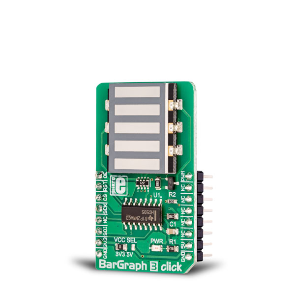
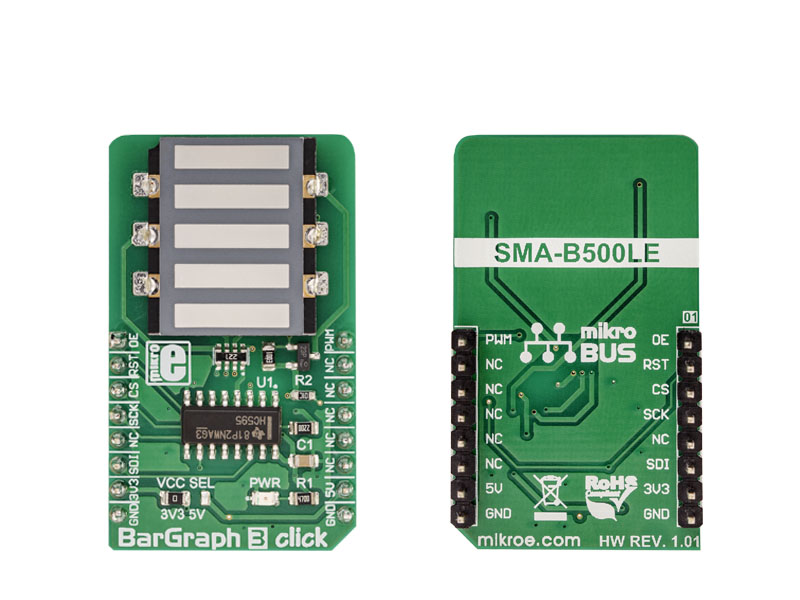
BarGraph 3 click is equipped with a five-segment LED bar graph display, notable for its strong and reliable illumination of the segments.

No Abuse Reported

Do you want to subscribe in order to receive notifications regarding "BarGraph 3 click" changes.

Do you want to unsubscribe in order to stop receiving notifications regarding "BarGraph 3 click" changes.

Do you want to report abuse regarding "BarGraph 3 click".

  • mikroSDK Library 2.0.0.0
  • Comments (0)
DOWNLOAD LINK RELATED COMPILER CONTAINS
mikroBasic PRO for ARM
  • lib
  • src
  • exa
  • hlp
  • hex
  • sch
  • pcb
  • doc
mikroBasic PRO for AVR
  • lib
  • src
  • exa
  • hlp
  • hex
  • sch
  • pcb
  • doc
mikroBasic PRO for dsPIC30/33 & PIC24
  • lib
  • src
  • exa
  • hlp
  • hex
  • sch
  • pcb
  • doc
mikroBasic PRO for FT90x
  • lib
  • src
  • exa
  • hlp
  • hex
  • sch
  • pcb
  • doc
mikroBasic PRO for PIC
  • lib
  • src
  • exa
  • hlp
  • hex
  • sch
  • pcb
  • doc
mikroBasic PRO for PIC32
  • lib
  • src
  • exa
  • hlp
  • hex
  • sch
  • pcb
  • doc
mikroC PRO for ARM
  • lib
  • src
  • exa
  • hlp
  • hex
  • sch
  • pcb
  • doc
mikroC PRO for AVR
  • lib
  • src
  • exa
  • hlp
  • hex
  • sch
  • pcb
  • doc
mikroC PRO for dsPIC30/33 & PIC24
  • lib
  • src
  • exa
  • hlp
  • hex
  • sch
  • pcb
  • doc
mikroC PRO for FT90x
  • lib
  • src
  • exa
  • hlp
  • hex
  • sch
  • pcb
  • doc
mikroC PRO for PIC
  • lib
  • src
  • exa
  • hlp
  • hex
  • sch
  • pcb
  • doc
mikroC PRO for PIC32
  • lib
  • src
  • exa
  • hlp
  • hex
  • sch
  • pcb
  • doc
mikroPascal PRO for ARM
  • lib
  • src
  • exa
  • hlp
  • hex
  • sch
  • pcb
  • doc
mikroPascal PRO for AVR
  • lib
  • src
  • exa
  • hlp
  • hex
  • sch
  • pcb
  • doc
mikroPascal PRO for dsPIC30/33 & PIC24
  • lib
  • src
  • exa
  • hlp
  • hex
  • sch
  • pcb
  • doc
mikroPascal PRO for FT90x
  • lib
  • src
  • exa
  • hlp
  • hex
  • sch
  • pcb
  • doc
mikroPascal PRO for PIC
  • lib
  • src
  • exa
  • hlp
  • hex
  • sch
  • pcb
  • doc
mikroPascal PRO for PIC32
  • lib
  • src
  • exa
  • hlp
  • hex
  • sch
  • pcb
  • doc

mikroSDK Library Blog

BarGraph 3 click

BarGraph 3 click

Native view of the BarGraph 3 Click board.

View full image
BarGraph 3 click

BarGraph 3 click

Front and back view of the BarGraph 3 Click board.

View full image

Library Description

The library initializes and defines SPI bus driver and drivers that offer a choice for writing data in registers and reading data from registers. The library includes functions for logging values on the BarGraph display. The user can enable and disable the chip with the function bargraph3_enable(), which is supported in the library.

Key functions:

  • void bargraph3_display(uint8_t ctrl, uint8_t dir, uint8_t counter) - Displays function
  • void bargraph3_enable(uint8_t state) - Functions for enabling the chip

Examples description

The application is composed of the three sections :

  • System Initialization - Initializes SPI module and sets AN, RST, CS and PWM pin as OUTPUT
  • Application Initialization - Initialization driver init, enable device and set PWM
  • Application Task - (code snippet) - Counter passes through the loop and logs the value of the counter on the bar graph di
void applicationTask()
{
    uint8_t bargraph_cnt;

    for (bargraph_cnt = 0; bargraph_cnt <= 5; bargraph_cnt++)
    {
        bargraph3_display(_BARGRAPH3_INCREASE_LED, _BARGRAPH3_DIRECTION_BOTTOM_TO_TOP, bargraph_cnt);
        Delay_1sec();
    }
}


Other mikroE Libraries used in the example:

  • SPI

Additional notes and information

Depending on the development board you are using, you may need USB UART click, USB UART 2 click or RS232 click to connect to your PC, for development systems with no UART to USB interface available on the board. The terminal available in all MikroElektronika compilers, or any other terminal application of your choice, can be used to read the message.

ALSO FROM THIS AUTHOR

I2C 1-Wire Click

0

I2C 1-Wire Click carries DS2482-800, a bridge device that performs bidirectional conversions between I2C masters and 1-Wire slave devices. These can be EEPROM chips, temperature sensors and similar devices that have momentary high source current modes.

[Learn More]

ccRF click

0

This is a sample program which demonstrates the use of ccRF click. Programmer uses RF module for communication between two development systems. Each module can be used as transmitter and receiver.

[Learn More]

I2C to CAN Click

0

I2C to CAN Click is a compact add-on board that contains I2C to CAN-physical transceiver, which extends a single-master I2C bus through harsh or noisy environments. This board features the LT3960, a robust high-speed transceiver that extends a single-master I2C bus up to 400kbps using the CAN-physical layer from Analog Devices. One LT3960 from SCL and SDA I2C lines creates equivalent differential buses (CAN) on two twisted pairs, while the second LT3960 recreates the I2C bus locally for any slave I2C devices on the other end of the twisted pairs. A built-in 3.3V LDO powers both the I2C and CAN lines from a single input supply from 4V to 60V. This Click board™ is suitable for industrial and automotive networking, remote sensor applications, and more.

[Learn More]